AStrutTie 사용설명서
AStrutTie 사용설명서 — 실제 화면 그림과 함께, 필요한 기능을 검색과 목차로 바로 찾을 수 있습니다.
제품 운영 도움말(HELP)을 통합한 공식 매뉴얼입니다. 더 자세한 답은 AI 상담에서 근거와 함께 받을 수 있습니다.
Introduction
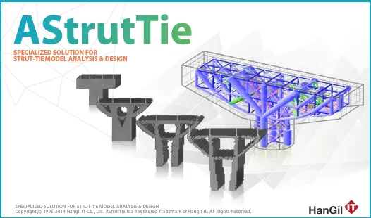
AStrutTie is a strut-tie model analysis/design software for concrete members with disturbed stress region(s). It enables users to design corbel (bracket), abutment/pier footing, bridge pier coping (pier cap), frame corner, anchorage zone, deep beam, etc. The software supports U.S (ACI, ASHTO) and Europe (EuroCode2) Codes and Specifications.
Why Strut-Tie Model
A concrete member can be classified into B-region(s) and D-region(s). D-regions are parts of structure in which the strain distribution is highly nonlinear. Most design practices for D-regions are mostly based on empirical approaches. The strut-tie model approach promotes a better under-standing of load transfer mechanisms and structural behavior and it improves the designers' ability to handle unusual circumstances including D-regions.
Optimum Solution for Strut-Tie Model Approach
AStrutTie is a powerful and practical analysis/design software for concrete members with D-region(s). The most appropriate strut-tie models can be constructed by considering the principal stress flows and/or evolutionary structural optimization (ESO) results. A specialized solver capable of handling any types of internally/externally (in)determinate strut-tie models is associated. The strut-tie model provisions of ACI 318-14 (2014), AASHTO LRFD (2014), and EC2 (2004) are applied.
Efficient Structural Modelings for Strut-Tie Model Design
For fast and efficient strut-tie model designs, multirole templates are provided for corbel (bracket), abutment footing, pier footing, bridge pier coping (pier cap), frame corner, anchorage zones with inclined and straight tendons, and deep beams with concentrated and distributed loads. The shapes of concrete members and truss models can also be generated by importing .dxf files. Advanced element sets representing truss mechanism, truss and arch mechanism, and fan action are provided.
Systems for Automated Design Checks and Structural Design Report
AStrutTie provides various automated design checks regrading the conditions for rebar requirement and strength verification of struts and nodal zones. Visual verifications of strength conditions are possible, too. A structural design report is generated automatically, and design results are examined by previewing the report. The structural design report is printed as a *.rtf or *.xlsx file.
Problems in Strut-Tie Model Analysis/Design of Structural Concrete
- Uncertainity in the construction of an appropriate strut-tie model due to lack of general and comprehensive specifications
- Inefficiency in the construction of strut-tie models representing load transfer mechanisms for multiple load combinations
- Enormous time and efforts for examining the suitability of a constructed strut-tie model that satisfies the strength condidtions of struts and nodes
- This manual is subject to change without notice to improve the product. -
Welcome!
#AStrutTie is a strut-tie model analysis/design software for concrete members with disturbed…
AStrutTie is a strut-tie model analysis/design software for concrete members with disturbed stress region(s). It enables users to design corbel (bracket), abutment/pier footing, bridge pier coping (pier cap), frame corner, anchorage zone, deep beam, etc. The software supports U.S (ACI, ASHTO) and Europe (EuroCode2) Codes and Specifications.
Need Strut-Tie Model Analysis or Design?
How about using AStrutTie?
The strut-tie model approach has been recognized as an efficient methodology for the design of all types of structural concretes with D-regions, and accepted in design codes globally. However, the design of a structural concrete with the approach requires many iterative numerical structural analyses, numerous graphical calculations, enormous time and efforts, and designer’s subjective decisions in terms of the construction of an appropriate strut-tie model, determination of required areas of struts and ties, and verification of strength conditions of struts and nodal zones.
Hangil has developed a design software AStrutTie that enables the analysis and design of tructural concretes efficiently and professionally by overcoming the aforementioned limitations of the strut-tie model approach. In the software, all the numerical programs that are essential in the strut-tie model analysis or design of a structural concrete, including finite element analysis programs for the plane truss and solid problems with all kinds of boundary conditions, a program for evaluating the axial rigidities of struts and ties of statically determinate and indeterminate strut-tie models, a program for determining, and a program for the graphical verification of strut-tie model’s appropriateness by displaying various geometrical shapes of struts and nodal zones, are loaded. Great efficiency and convenience during the application of the strut-tie model approach may be provided by the various graphics environment-based functions of the software.
Features of AStrutTie
#Ease of Use
Ease of Use
- Intelligent graphical user interfaces
- Visualizations by using view option windows
- U.S customary and metric(SI) units
- Tabular and dialog inputs
- 2-D on-screen graphics
- Graphical display of applied loads, boundary conditions, and structural analysis results
- Visual and tabular verifications of strength conditions of struts and nodes
- 9 templates for typical D-regions and structural members
- Design checks on user interfaces
- Preview of structural design report
- Report output as Word (*.rtf) or Excel (*.xlsx) file
- Importation of *.dxf file for modeling of solid and truss structures
- Verified (in)determinate strut-tie models for templates
- Unconstrained solid and truss modelings for strut-tie model design
Support Items of Templates
Corbel (Bracket)
- Automatic Determination of Location of STM Node sub jected to Applied Loads
Abutment/Pier Footing
- Spread and Pile Footings bounded by Springs
- Automatic Conversion of Applied Loads to Pile Reactions
- Automatic Assignment of Soil/Pile Reactions to Spring Constants
- Automatic Construction of STM according to Pile Locations and Number of Pile
- Automatic Determination of Pile Locations by Inputing Number of Pile
Bridge Pier Coping (pier cap)
- Automatic Construction of STM by Selecting Load Transfer Mechanism (Arch, Vertical Truss)
- Automatic Construction of STM according to Number of Concentrated Load Point
Frame Corner
- Four Separate Templates according to Moment Types and Corner Shapes
- Four Basic Types of Strut-Tie Models recommended by EC2
Anchorage Zone
- Automatic Construction of STM considering AASHTO LRFD's Bursting Force Location
- Tendon Layout, and Number of Anchor Plate
Deep Beam with Concentrated Loads
- Three Types of FIB Strut-Tie Models according to Shear Span-to-Effective Depth Ratio (Arch, Vertical Truss, Combined)
- Automatic Construction of STM according to Number of Load Point, Symmetric/Asymmetric Load,
and Symmetric/Asymmetric Geometrical Shape
Continuous Beams with Distributed Loads
- Automatic Construction of STM resulting in Vertical and Horizontal Reinforcing Bars
- STM for Continuous Deep Beams
Included Design Codes
- AASHTO LRFD (2014)
- ACI 318-14 (2014)
- EC 2 (2004)
Items for Design Checks
- Strength Verification of Concrete Struts
- Required Areas of Steel Ties (Flexural Rebars, Shear Rebars, Supplementary Rebars)
- Strength Verification of Nodal Zones
- Anchorage of Rebars at Critical Nodal Zones
- Minimum Reinforcement Ratio for Serviceability
Convenient Editing Tools for Truss Structure
- Versatile Editing Tools supplied by the Nine Templates
- User-based General Editing Tools (cut, copy, paste, delete, find, divide, offset, move, stretch, mirror, rotate)
- Object Osnap (End, Mid, Cross, Near, Perpendicular Point)
- Guidelines and Grid Points
- STM Constructed from Boundary Lines of Concrete Member
- Automatic Check of Object Overlaps
- Modeling of Structures by Dxf Import/Export
Functions of Truss Solver
- Analysis of Internally/Externally Determinate/Indeterminate Truss Structures
- Inclined, Horizontal, and Vertical Restraints by Spring, Hinge, and Roller
- Determination of Required Areas and Forces of Struts and Ties by Iterative Technique
- Safety Evaluation of Existing Structural Members by Assigning Steel Tie Areas
- Calculation of Available Areas of Struts and Ties
- Determination of Average Principal Tensile Strain of Reinforcing Bars crossing Perpendicularly to Concrete Strut by Iterative Technique
- Automatic Transformation of Distributed Forces to Nodal Forces
Functions of Plane Solid Solver
- Analysis of Plane Stress and Plane Strain Problems
- Inclined, Horizontal, and Vertical Restraints by Spring, Hinge, and Roller
- Optimized Mesh Generater according to Concrete Member Shape
- Automatic Transformation of Distributed Forces to Nodal Forces
- Calculation of Principal Stresses and Directions
- Relative Lengths and Colors of Principal Stresses along Principal Directions
- Implementation of Evolutionary Structural Optimization Technique
License and copyright
#AStrutTie, User Manual. Copyright © Hangil IT ®software.
AStrutTie, User Manual. Copyright © Hangil IT ®software.
The software AStrutTie, described in this users manual, is furnished under a license agreement.
The software may be used only in accordance with the terms of the license agreement. Information in this document is subject to change without notice.
License and copyright
If you do not agree with the terms of the following Disclaimer and License Agreement, and didn’t install & activate it, please send a e-mail to support@aroad.co.kr within 30 days. You can be full refund of software cost and sales tax.
Disclaimer
This software should be used only from experienced and licensed professional engineers. The software must be considered as a helping tool for the designer engineer, and can never replace the knowledge, the experience and the judgment of a professional engineer. The user of this software must understand that no matter how advanced and well checked this software is, he should carefully check the results and take responsibility of their use.
Copyright
This software is owned by Hangil IT Republic of Korea, and it is protected by Republic of Korea Copyright Laws and International Treaty Provisions. This software and the accompanying materials, must be treated like any other copyrighted material (e.g. book). It is allowed although to make one copy of the Software for backup or archive purposes. You may not copy and distribute the accompanying materials. It is strictly prohibited by law unauthorized reproduction or resale of this software product and the accompanying materials.
Software License
This is a legal agreement between the legal user of this software and Hangil IT Republic of Korea. By installing this software you agree to be bound by the terms of this agreement. If you do not agree to the terms of this agreement then do not install this software and return within 30 days after purchase, for a fully refund of your payment.
Scope of License
Each licensed copy of AStrutTie must be used either on a single computer, or installed on a single workstation used non-simultaneously by multiple people, but not both. This is not a concurrent use license.
You may not rent or lease this software. You may not modify, adapt, translate, reverse engineer, decompose, or disassemble the software. Any violation of this agreement terminates your right to use this software.
Liability Limitations
AStrutTie, in no event shall be liable for any damages whatsoever (including without limitations, damages for loss of business profits, business interruption, or any other loss) arising of the use of this software. Hangil IT Republic of Korea makes no warranties, either expressed or implied, as to the quality or performance of this software, that the results and calculations of this software will meet your requirements, or that the operation of this software will be error free.
This software is a helping tool to aid you in the design. The results of this software must be reviewed and interpreted from experienced licensed engineers, and by no means constitute an acceptable engineering design.
AStrutTie and related documentation are provided "AS IS" and without warranties as to performance or merchantability or any other warranties whether expressed or complied. Because of the various hardware and software environment into which this software may be put, no warranty of fitness for a particular purpose is offered. Under no circumstances shall Hangil IT Republic of Korea and its personal be liable for any direct or indirect, incidental special or consequential damages resulting from the use or inability to use of this software or related documentation, even if Hangil IT has been advised of the possibility of such damages.
This agreement shall be governed by Republic of Korea laws. If for any reason a court or competent jurisdiction finds any provision of this agreement, or portion thereof, to be unenforceable, that provision of the agreement shall be enforced to the maximum extend permissible so as to effect the intent of the parties, and the remainder of this agreement shall continue in full force effect. If this license is too restrictive with the laws of your country, do not use this software and return within 30 days after purchase, for a fully refund of your payment.
Hangil IT Republic of Koera,
e-mail: support@aroad.co.kr
Internet: ../english/
Trial Request
#Product Request and Software Download
Product Request and Software Download
www.aroad.co.kr/english/customer/astruttie_trial.asp

- Write your E-mail account
- Write your Company
- Write your Name
- Write your Tel.
- Choose the Nation and Product
- Click < AStrutTie Request > Button
We will sent download link and product key by e-mail within a day.
How to Order
#AStrutTie Online Shop - https://service.aroad.co.kr/shop/astruttie/buy.do
AStrutTie Online Shop - https://service.aroad.co.kr/shop/astruttie/buy.do

- Choose an AStrutTie family
- Choose an Optional
- Click Buy Now --> Go to Paypal
- If you would like to pay by invoice, please send us an e-mail. ( support@aroad.co.kr )

- A payment information email will be sent when payment is complete.
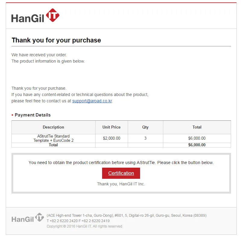
- Click < Certification > Button

- Write your Company
- Write your Tel.
- Choose the Nation
- Click < AStrutTie Request > Button
We will sent download link and product key by e-mail within one business day.
2. Pricing
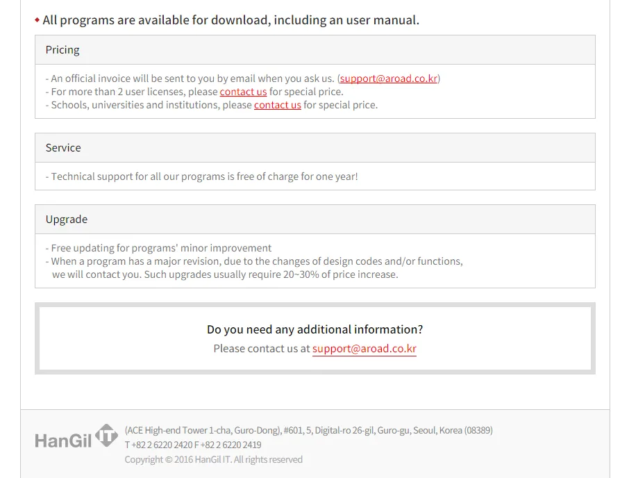
- For more than 2 user licenses, please contact us for special price.
- Schools, universities and institutions, please contact us for special price.
Install Process, Activation and Standard Uer account
#Install process of AStrutTie
Install process of AStrutTie
When you install AStrutTie, please must login the PC with administration authority.
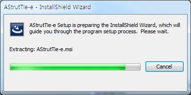
A. Aftter unzip the AStrutTie Install file, Click Setup.exe .
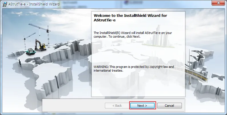
- Click the Next Button
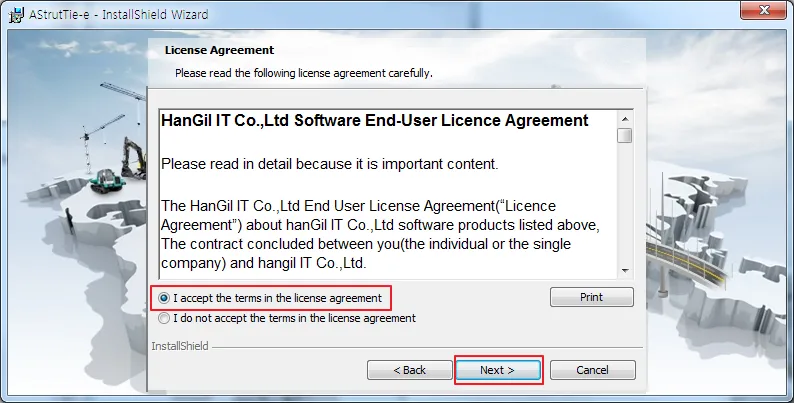
- Select ' I accept the terms in the license agreement
- Click the Next Button
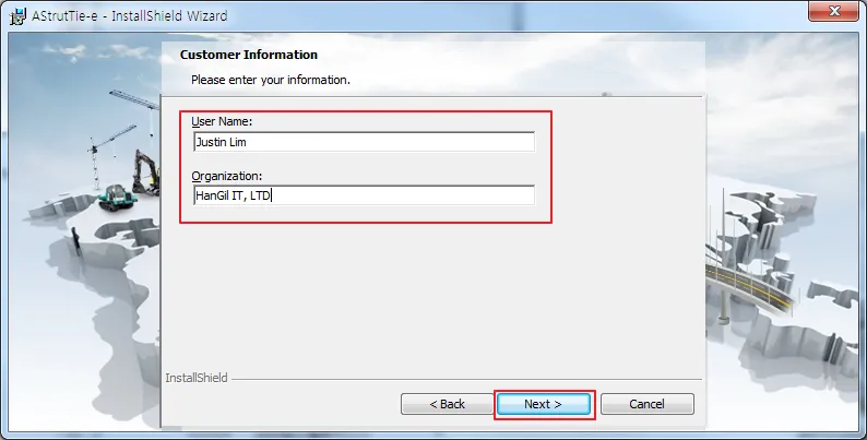
- Write User Name and Orgnization
- Click the Next Button
- Click the Next Button
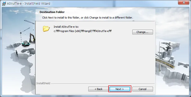
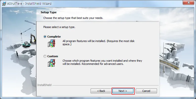
- Select Complete or Custom
- Click the Next Button
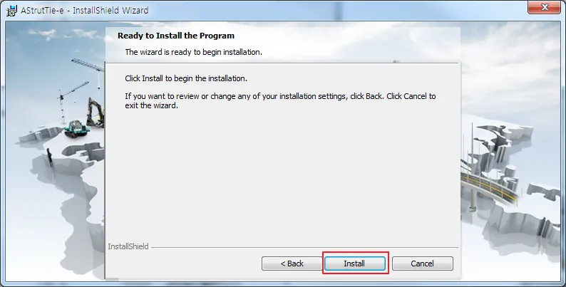
- Click the Install Button
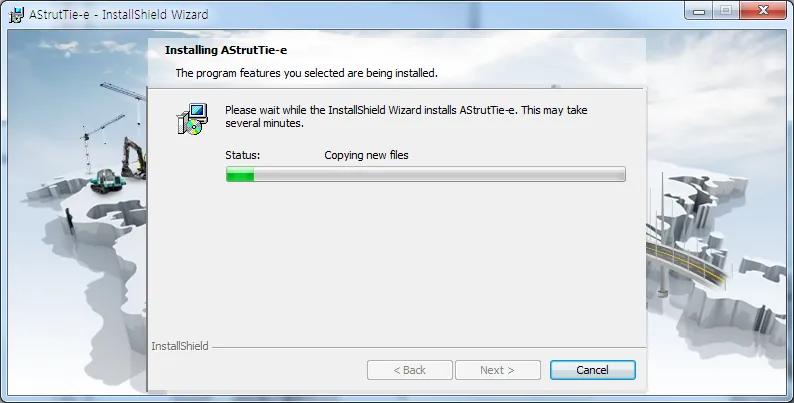
- Required selection 'Lock Driver Install'
- Click the Finsh Button, Lock Driver will Install.
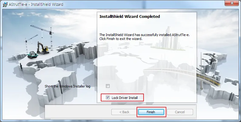
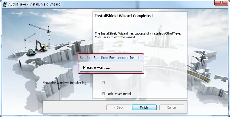
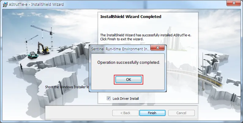
- Click the OK Button, Install is end.
2. Activation of AStrutTie
When you activate AStrutTie, please must keep online internet.
If you use firewall, please add it to your firewall.
- activation.aroad.co.kr
- service.aroad.co.kr
- www.aroad.co.kr
- When run AStrutTie in first time, You must do Software Lock Activation and Cetification
1. input Product Key ( received by E-mail )
2. Click < Product activation key issue>
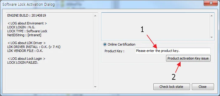
- After Software Lock Activation, Run AStrutTie. Install is done.
3. If you use windows standard user account
Please try according to the process below.
1. When you install AStrutTie, please must login the PC with administration authority.
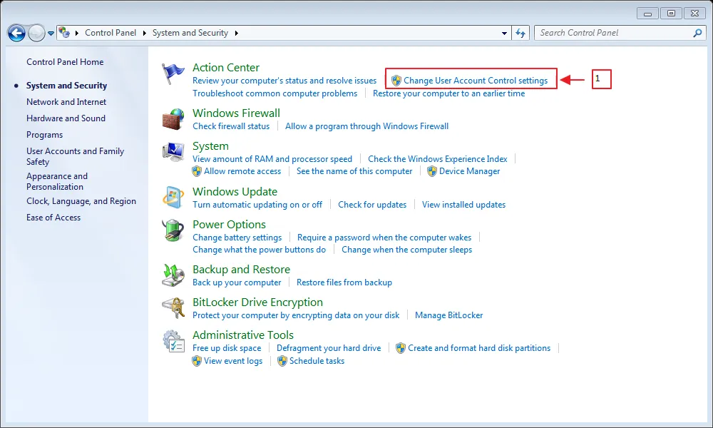
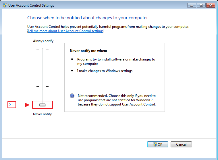
2. Go to Control Panel > Change User Account Control settings > Never notify
< OK > Click
Product Classification and System Requirement
#Product Classification
Product Classification
Classification
Standard
Professional
Trial
(30 days free)
Stress Flow Analysis
O
O
O
Determinate Truss Analysis
O
O
O
Indeterminate Truss Analysis
O
O
O
ESO (Evolutionary Structural Optimization)
O
O
Structure Template (Optional)
O
O
O
Structure Template Edit (Optional)
O
O
O
Structure Model dxf import, export
O
O
Truss advance elements
O
O
Determinate of Required Area of Strut
O
O
O
Design Review
O
O
O
Metric (SI) Unit
O
O
O
U.S Customary Unit (Scheduled for 2017)
O
O
ACI 318M Code
O
O
O
AASHTO-LRFD Spec. (Optional)
O
O
O
Eurocode 2 (Optional)
O
O
O
Graphical Display of Structure Analysis Results
O
O
O
Report Preview
O
O
O
ACI Report File Save
O
O
AASHTO Report File Save (Optional)
O
O
Eurocode 2 Report File Save (Optional)
O
O
2. System Requirement
Software
Microsoft Word2007 or higher
Microsoft Excel2007 or higher
Network
Internet Online
Processor
1GHz 32bit(x86) or higher
Operating System
Microsotf Window7(32, 64bit) English Version
Memory
1GB recommended
Disk Space
200MB
Input Device
Mouse, Keyboard
Precautions
1.Need Installation of Microsoft Excel for *.xlsx File Output
2.Need Internet Online for Activation of AStrutTie
3.Certify Perfect Activation of AStrutTie in Microsoft Window7 for English
(32, 64bit - Some of AStrutTie functions may not work well on other Operating System.)
Quick Start for Strut and tie Model Design

Design Steps Using Strut-Tie Model
#In the Beginning Mode, the design conditions of concrete member including the geometrical…
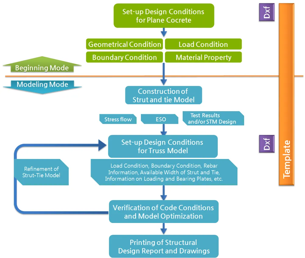
In the Beginning Mode, the design conditions of concrete member including the geometrical shape, load and boundary conditions, material properties, and load combinations are fixed.
The design conditions are used in the Modeling Mode and design steps of strut-tie model method that require the finite element analysis of unreinforced plane concrete and truss structures.
Modeling of Member Geometry
#The geometrical shape of concrete member is constructed in the Beginning Mode. The geometrical…
The geometrical shape of concrete member is constructed in the Beginning Mode. The geometrical shape is constructed by 1) direct drawing, 2) importing a . dxf file, 3) using a Template. For direct drawing, the functions Add Nodes and Add Elements are used. The boundary lines and truss model of the concrete member are generated by importing a . dxf file. The geometrical shape, evolutionary structural optimization, stress flow, and truss model can be generated automatically by using a Template.
1. Importation of .dxf file
The geometrical shape of concrete member and truss model generated as .dxf files by using drawing tools including Autocad can be imported by clicking FILE-Import. In generating a .dxf file, all drawings must be constructed as lines, and the boundary of concrete member and truss model must be named as ‘ Out ’ and ‘ Truss ’ respectively.
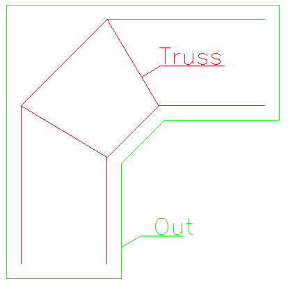
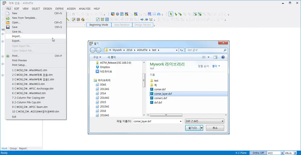
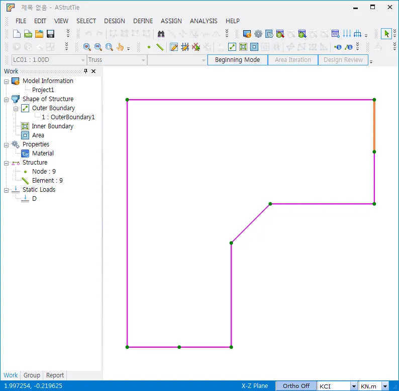
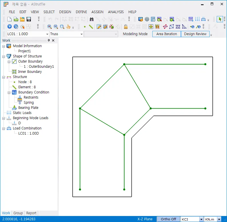
By importing a .dxf file, the boundary of concrete member and truss model are constructed automatically as follows.
2. Use of Template
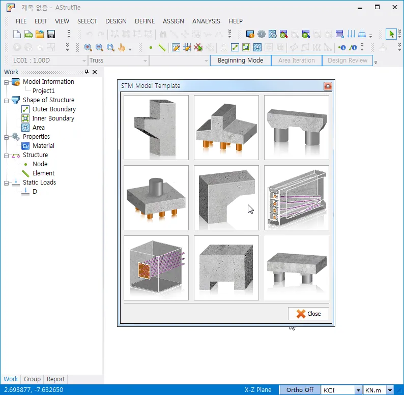
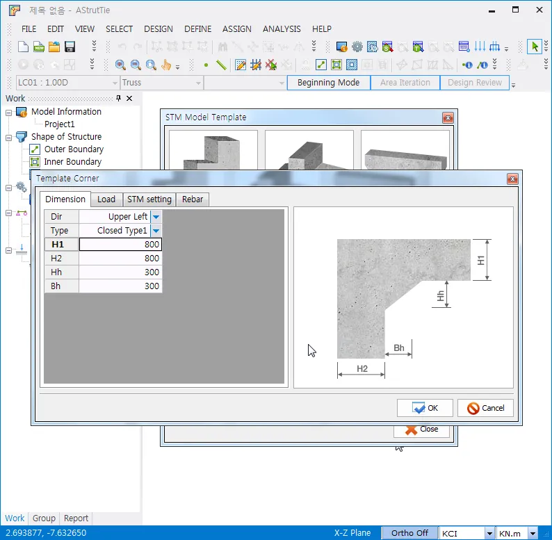
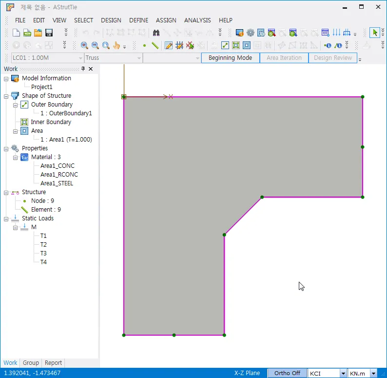
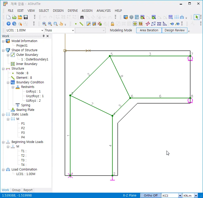
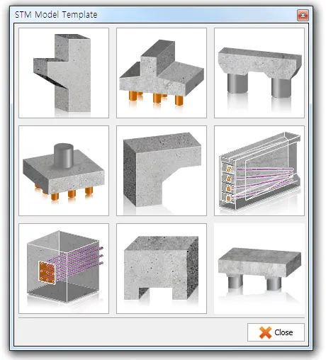
The geometrical shape of concrete member and truss model are generated by clicking FILE-New From Template and selecting one of the provided templates shown below . The basic information on the geometrical shape including thickness, width, and height must be input.
3. Direct Drawing
An example for constructing the boundary of concrete member is illustrated. The boundary can be constructed by using the functions Add Nodes or Add Elements. By clicking DESIGN-Add Elements, the coordinates of end points of lines are input in Edit Coordination (Dialog) as follows.
1.1 , 1.1 enter
1.9 , 1.1 enter
1.9 , 1.5 enter
1.9 , 1.9 enter
0 , 1.9 enter
0 , 0 enter
0.4 , 0 enter
0.8 , 0 enter
0.8 , 0.8 enter
1.1 , `1.1 enter
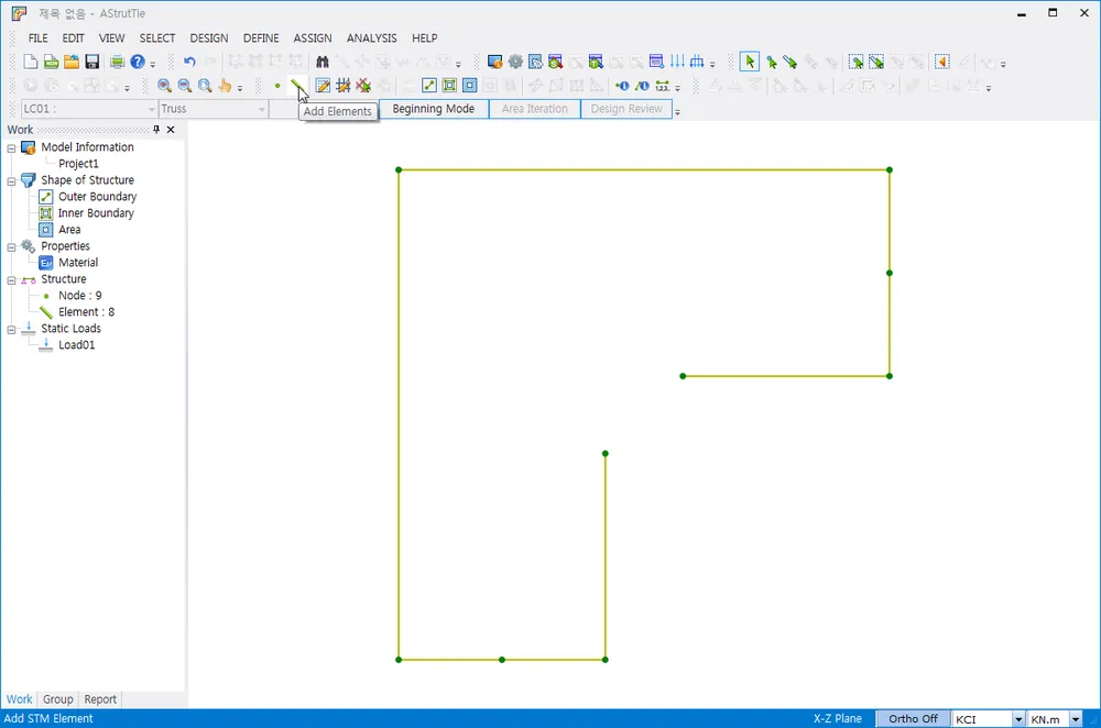
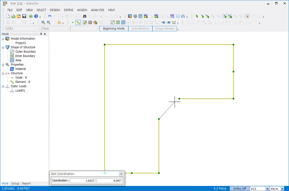
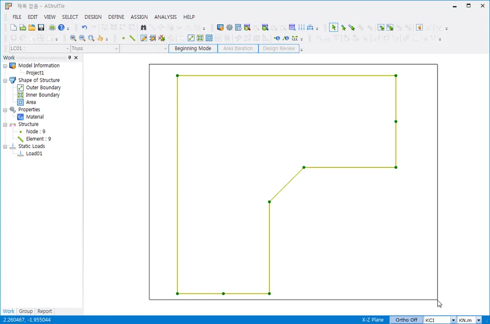
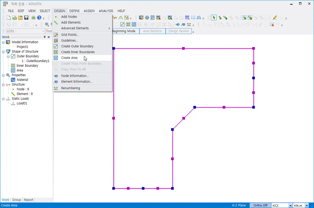
Once the boundary is constructed, the boundary must be recognized as the boundary of plane concrete member by clicking DESIGN-Create Outer Boundary.

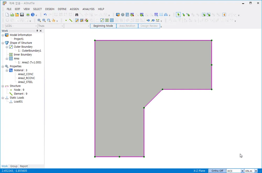
By clicking DESIGN-Create Area, the area surrounded by the outer boundary is set to designate the information of plane concrete member including member thickness, compressive strength of concrete, and yield strength of reinforcing bars.
Application of Loads
#Two methods for applying loads are provided in the program.
Two methods for applying loads are provided in the program.
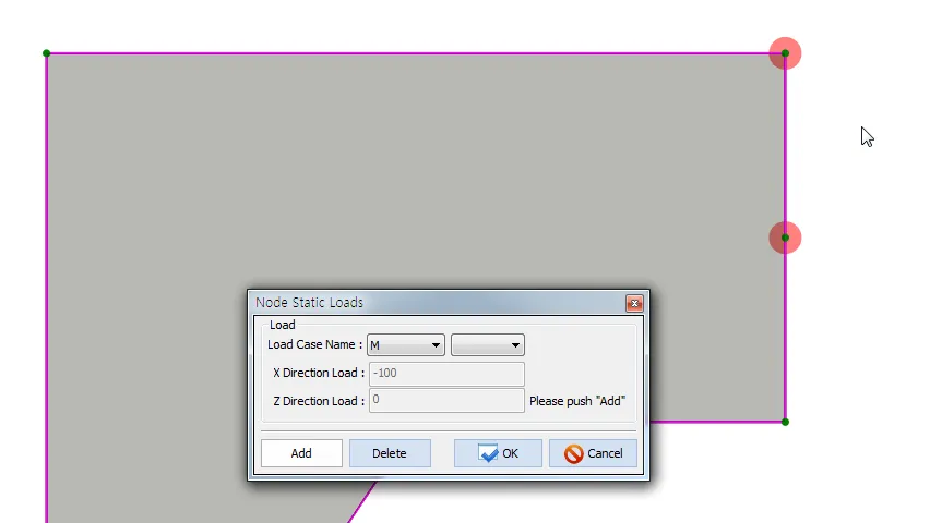
1. Node Static Loads
External loads are assigned by clicking ASSIGN-Static Load. After selecting nodes and elements, the following figure appears.
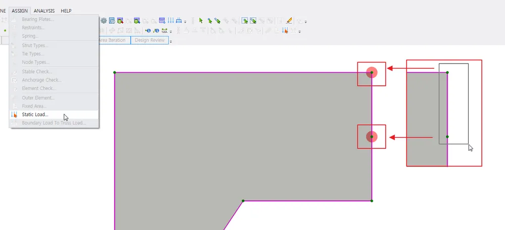
After clicking Static Load, the Node Static Loads (Dialog) appears by clicking the right button of mouse. And then, loads are assigned by clicking Add button.
2. Element Static Loads
After selecting nodes and elements, the following figure appears.
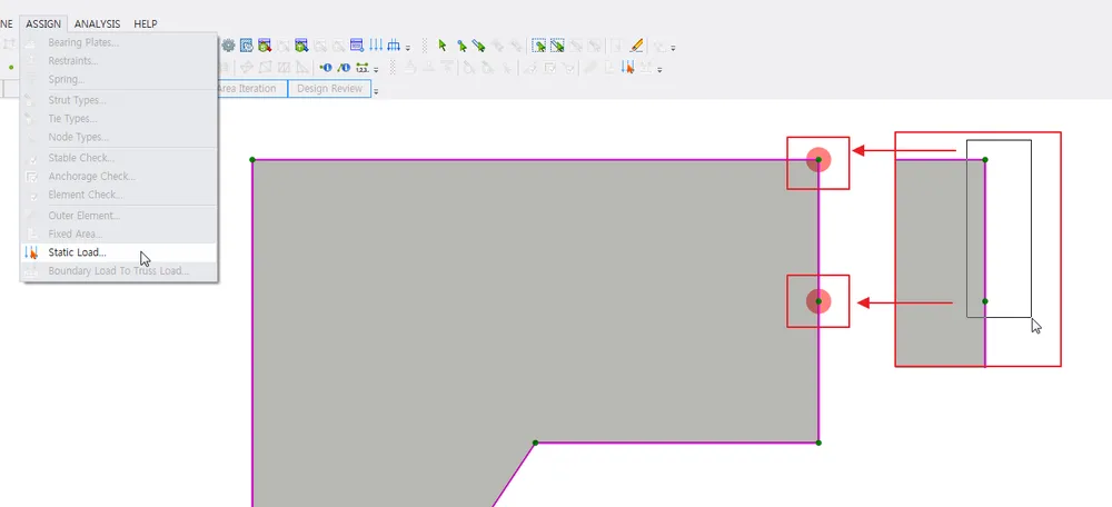
After clicking Static Load, the Element Static Loads (Dialog) appears by clicking the right button of mouse when the color of node changes from green to red. And then, loads are assigned by clicking Add button.
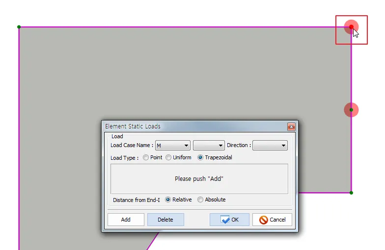
And then, the direction of load and load type must be selected. Three load types (point load, uniform load, and trapezoidal load) are available. An example for inputting trapezoidal load is shown below.
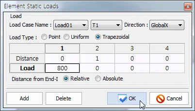
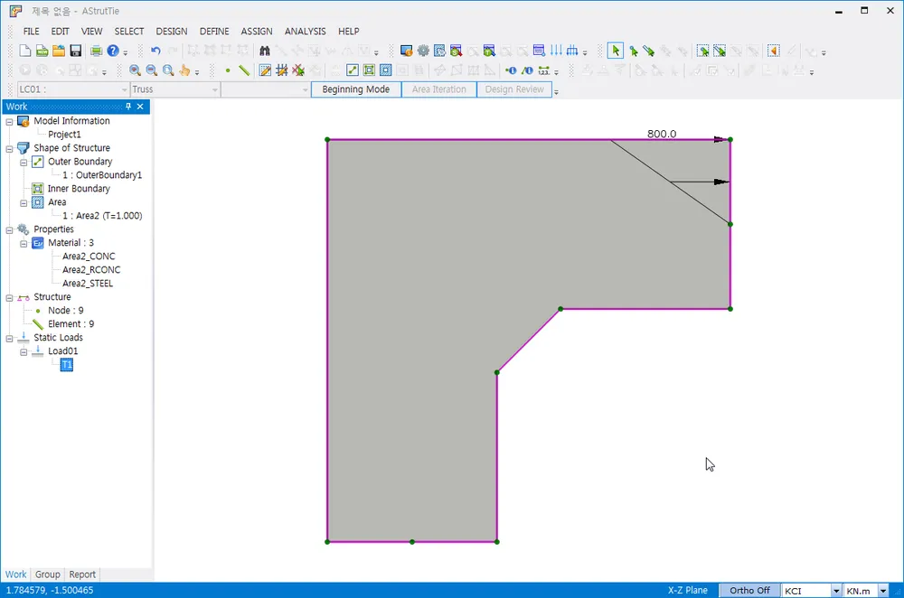
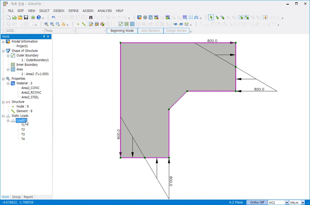
By repeating the inputting, multiple trapezoidal loads can be input as follows.
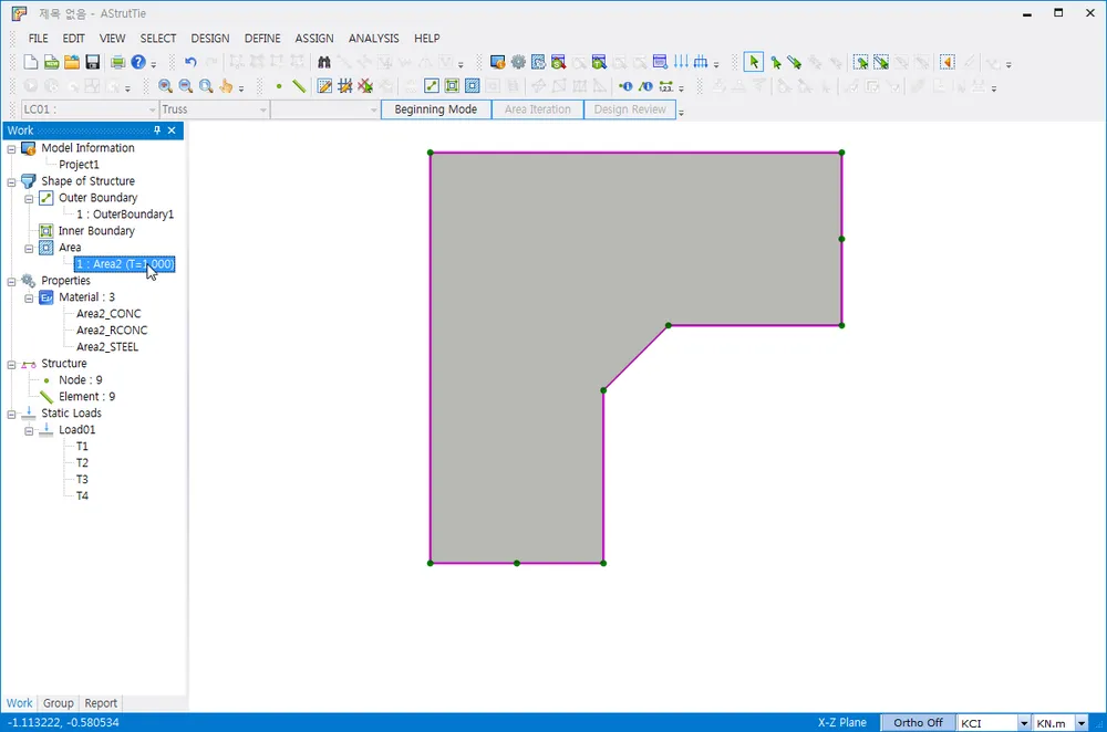
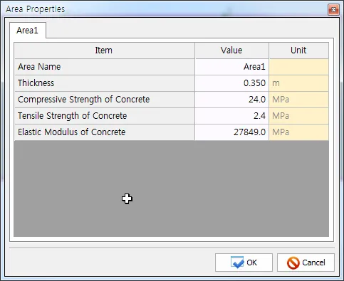
The material properties can be altered in Area Properties shown below.
Structural Analysis for ESO & Stress Flow
#The window transforms to the Modeling Mode for numerical structural analysis after imposing…
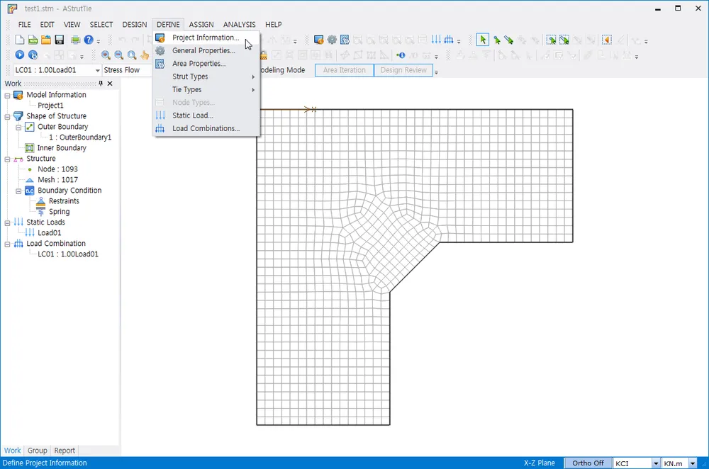
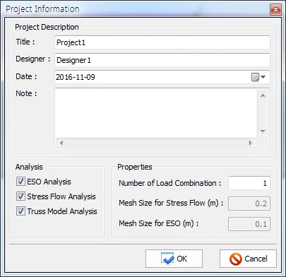
The window transforms to the Modeling Mode for numerical structural analysis after imposing loads on a concrete member. The Modeling Mode consists of ESO, Stress Flow, and Truss. The finite element model of a concrete member for ESO and Stress Flow analyses is constructed by using a mesh generator. The mesh size is setup by clicking DEFINE-Project Information.
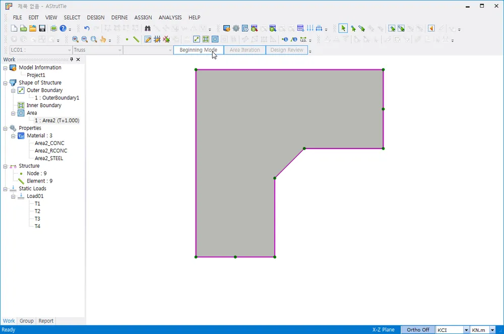
Followings are the figures that illustrate the finite element modeling of a concrete member. After clicking Beginning Mode and selecting Modeling Mode-Stress Flow, DEFINE-Project Information (Dialog) needs to be activated to alter the mesh size. The loads inserted by clicking Static Load are switched to nodal forces automatically.
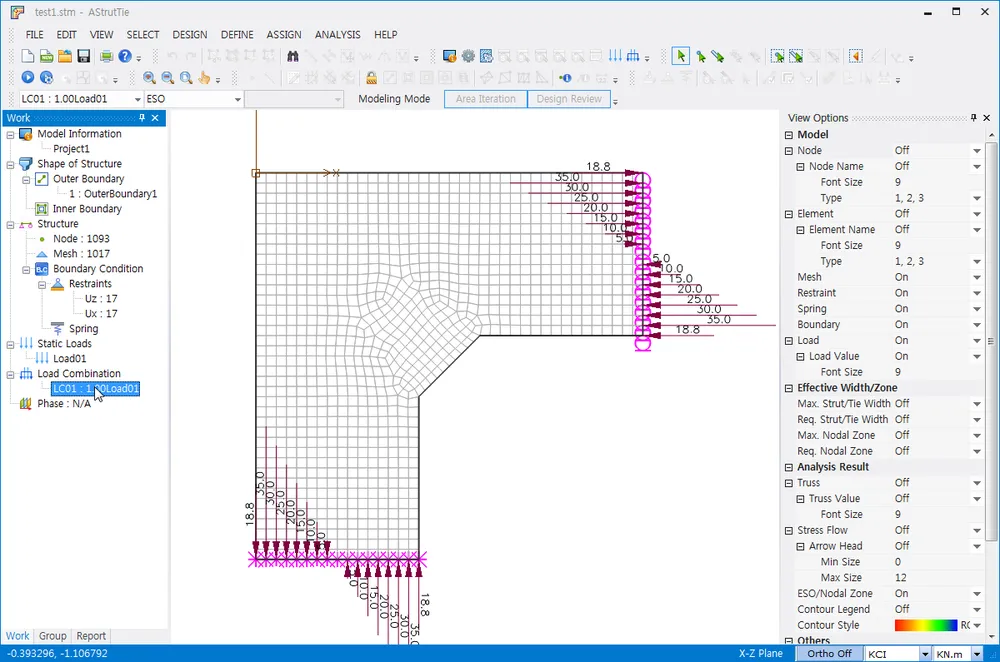
If the mesh size is changed, the boundary conditions must be updated. For this, the View Options Window must be activated and Node must be On, as shown below.
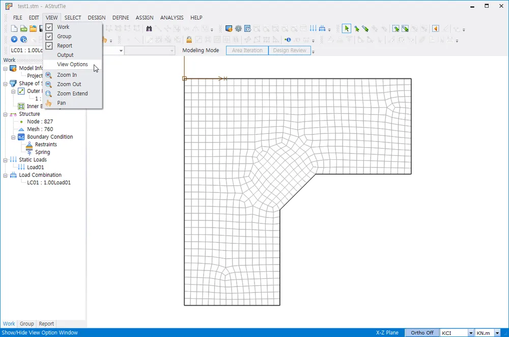
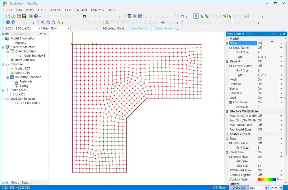
After selecting the nodes on which restraints must be imposed, the boundary conditions are setup by clicking ASSIGN-Restraints.
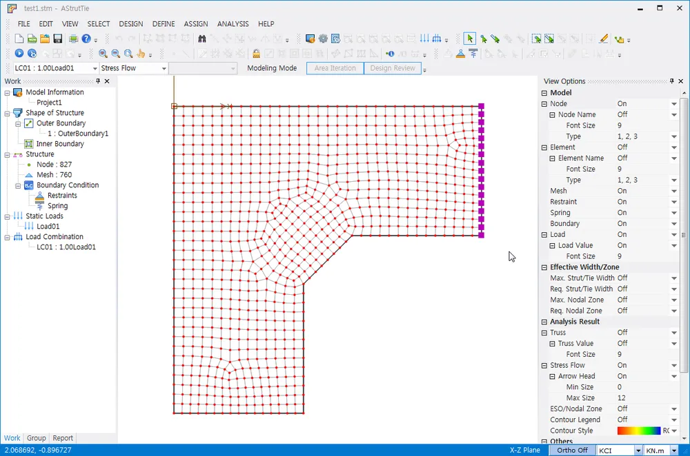
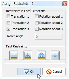
An example is shown below.
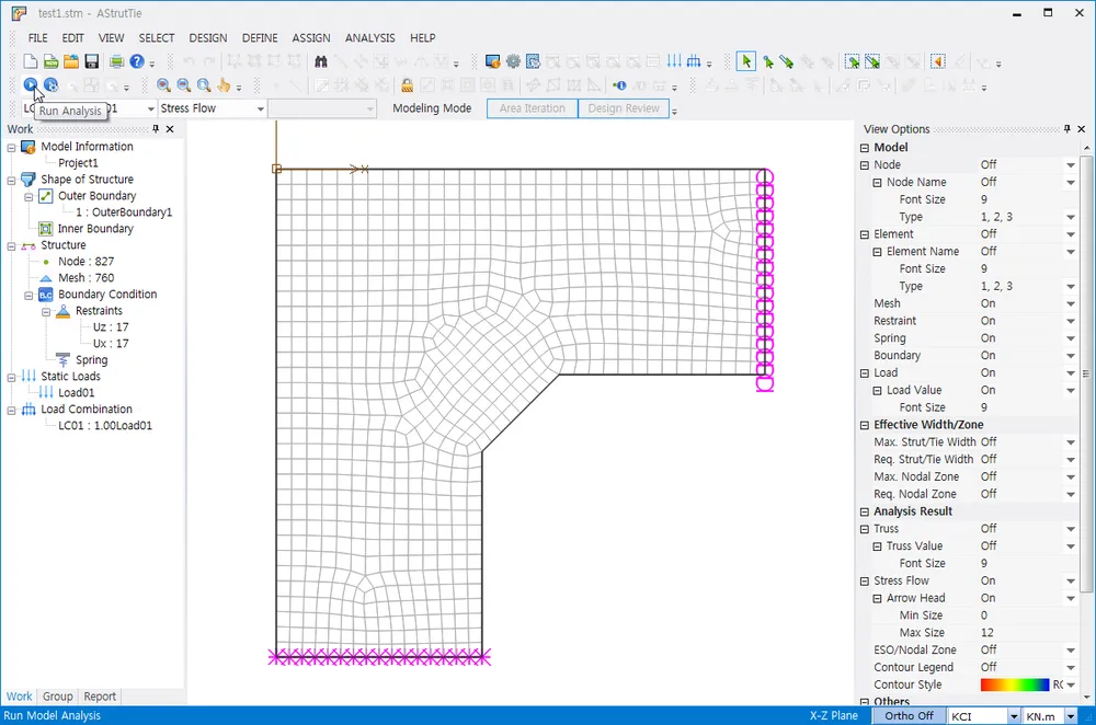
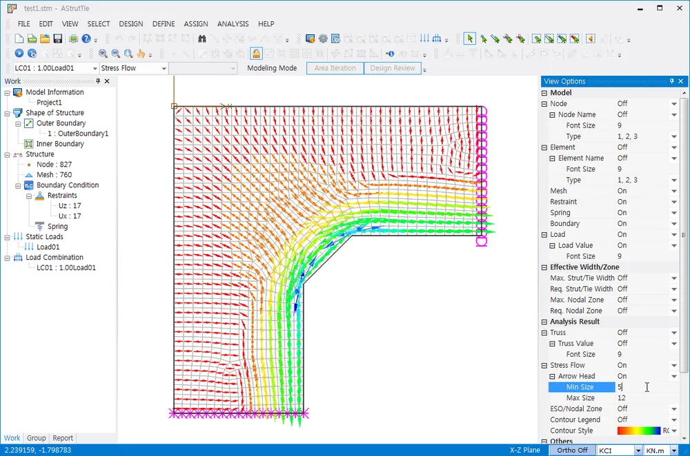
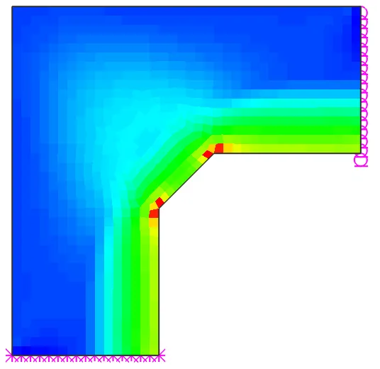
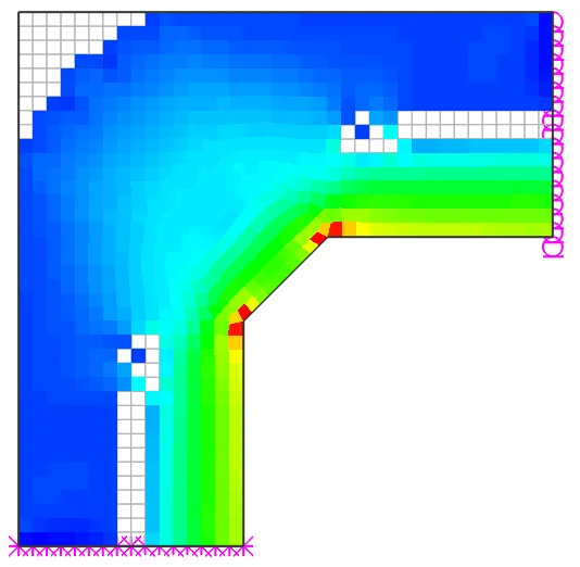
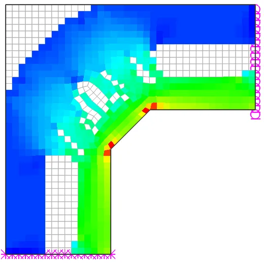
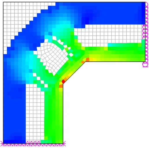
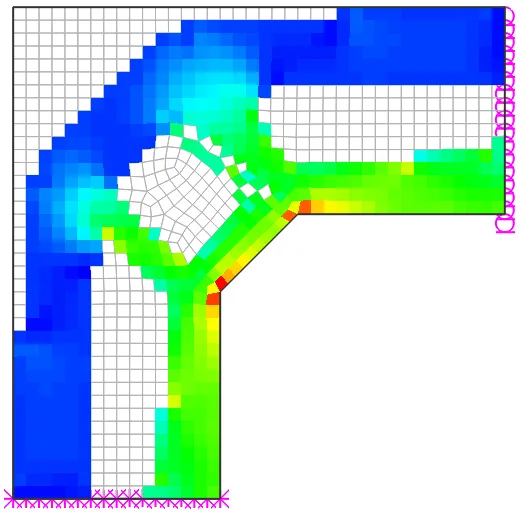
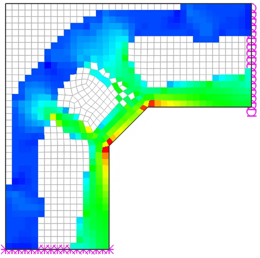
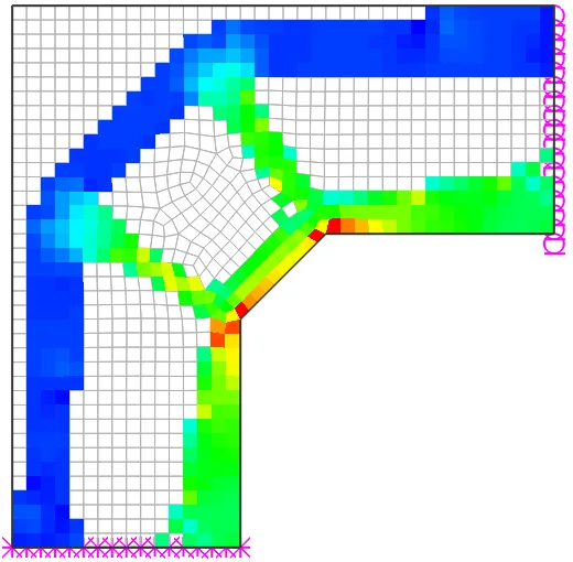
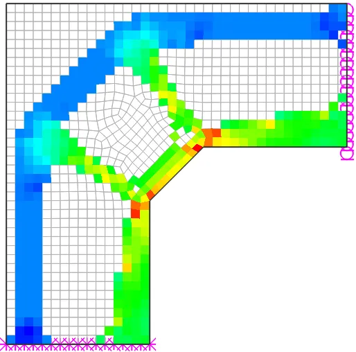
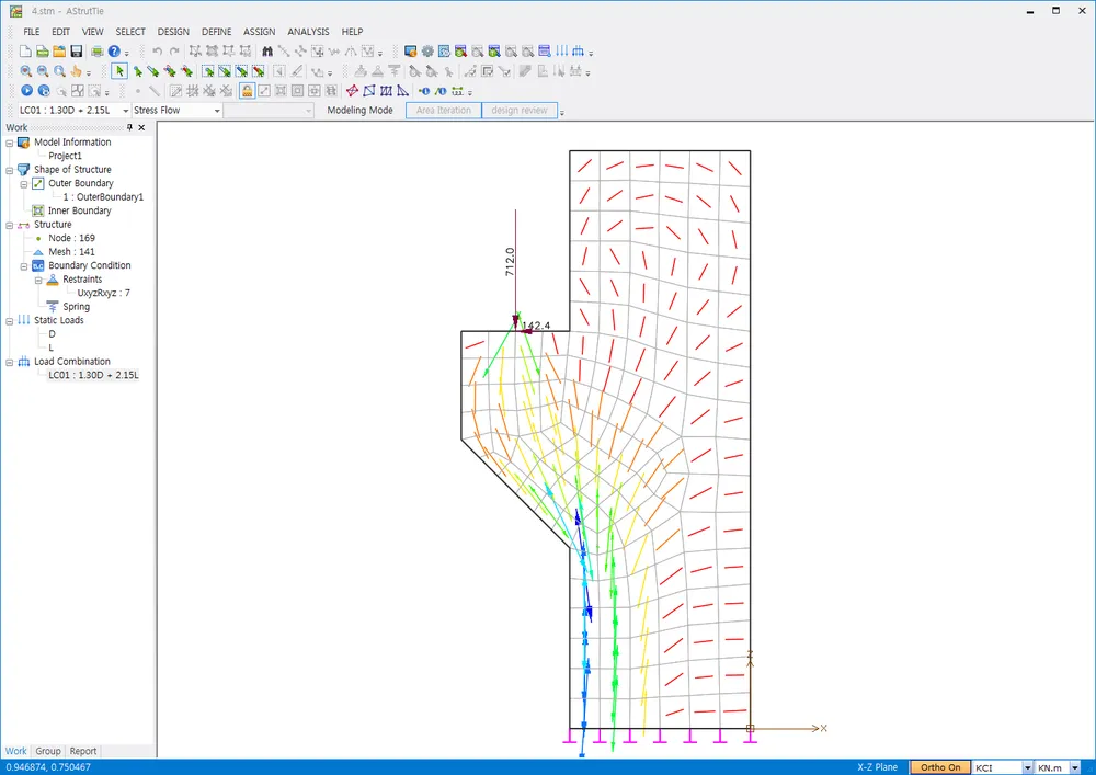
And then, by clicking ANALYSIS-Run Analysis the finite element linear elastic analysis is conducted for checking the compressive principal stress trajectories. The left figure shown below is an example showing the stress trajectories. In the same way, by clicking ESO (instead of Stress Flow) and completing the necessary modifications and inputs in DEFINE-Project Information (Dialog) and ASSIGN-Restraints, the finite element analyses are conducted for checking the approximate load paths by the evolutionary structural optimization technique. The right figure shown below is an example showing the results of the optimization.
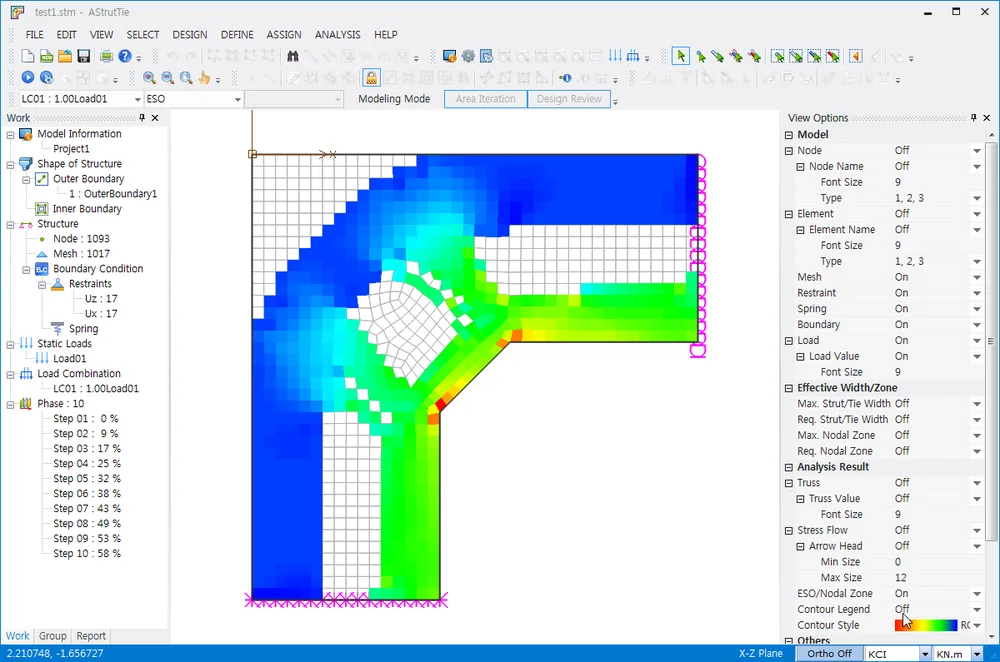
More results of the optimization are shown below.
Modeling and Analysis of Truss Model
#After the finite element analyses for the stress trajectories and evolutionary structural…
After the finite element analyses for the stress trajectories and evolutionary structural optimization, Truss Model need to be selected. The boundary elements of truss model are generated based on the outer boundary of concrete member by clicking DESIGN-Create Truss From Boundary (Dialog). In the dialog, the distance between the boundary of concrete member and the boundary elements of truss model is set.
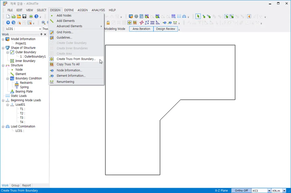
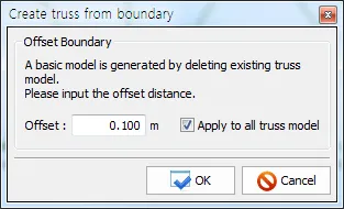
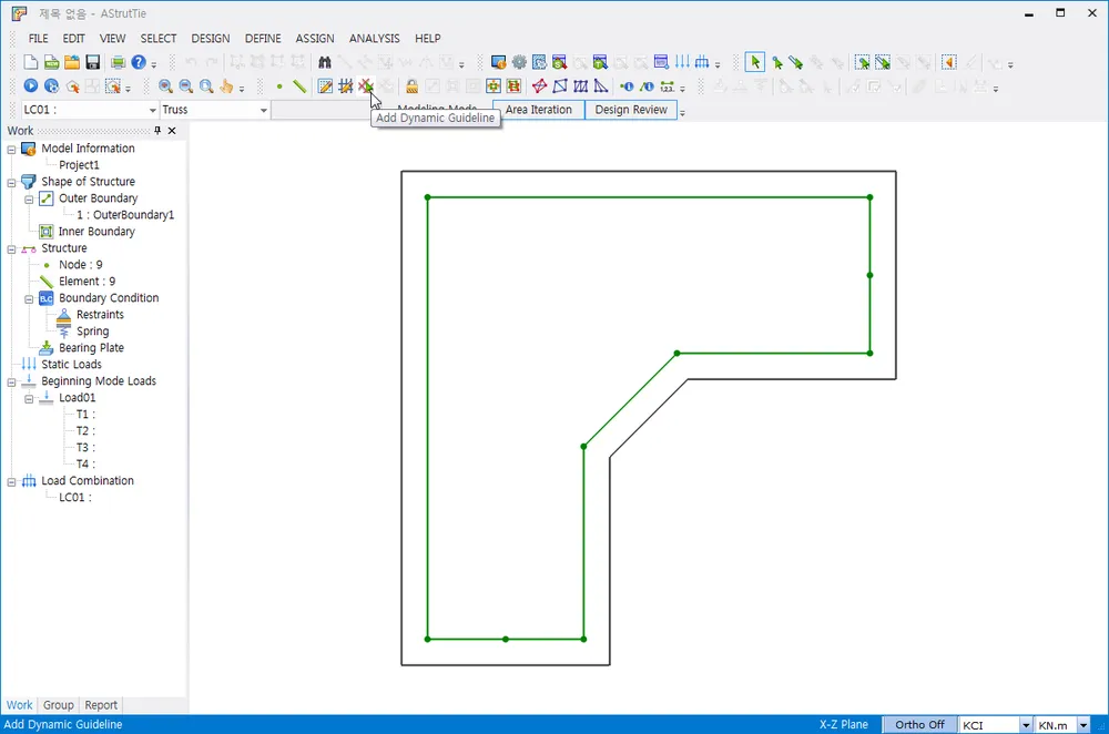
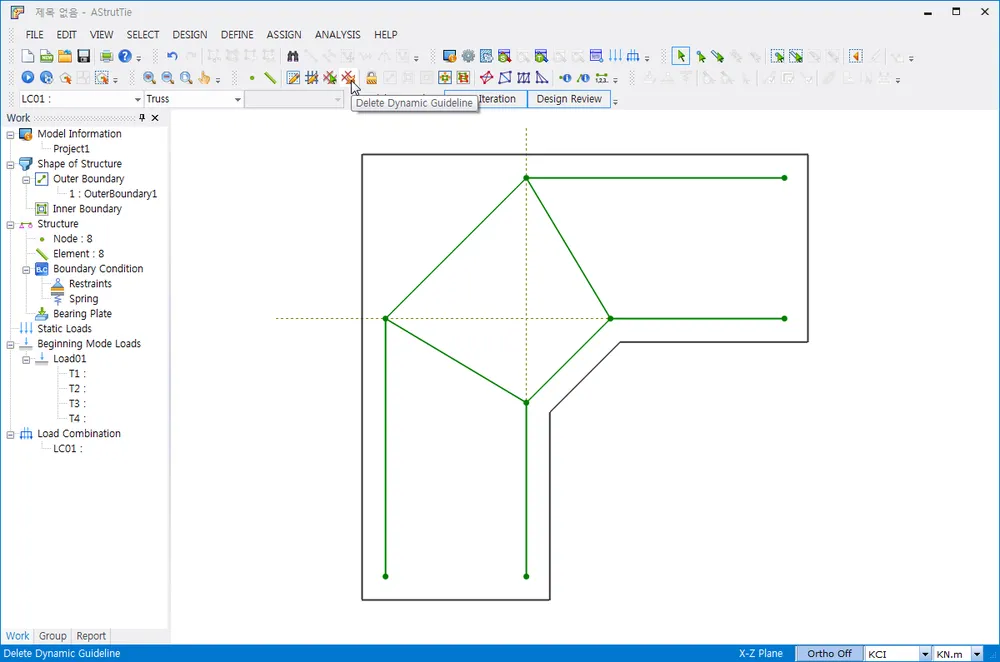
The boundary elements of truss model can be edited depending on designers ’ decision. To make the editing easier, the functions Guide Line and Grid are provided. The orthogonal guide lines are available by clicking F8 key. An example to generate the boundary elements of truss model by clicking Dynamic Guide Line is shown below.
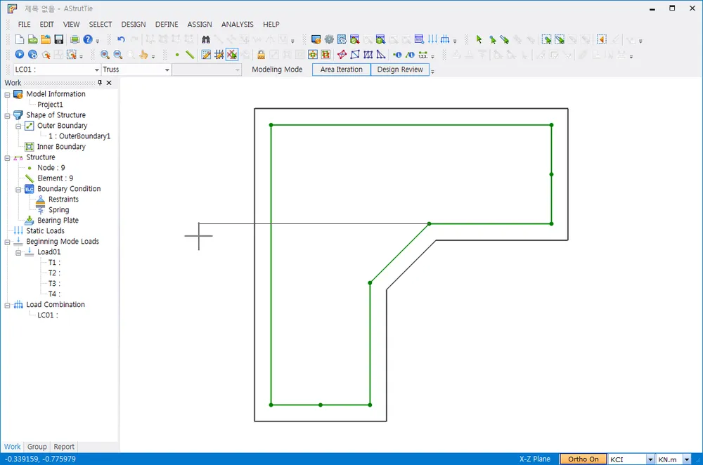
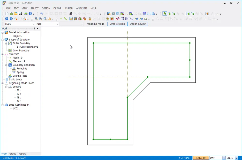
Based on the guidelines and by using Add Elements, additional elements of truss model are generated as shown below.
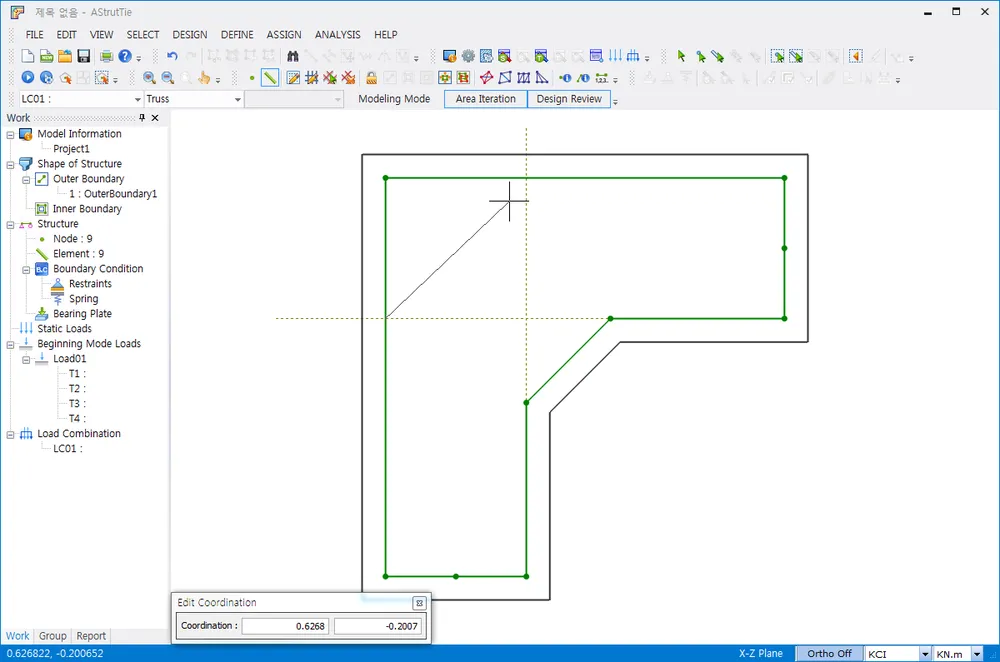
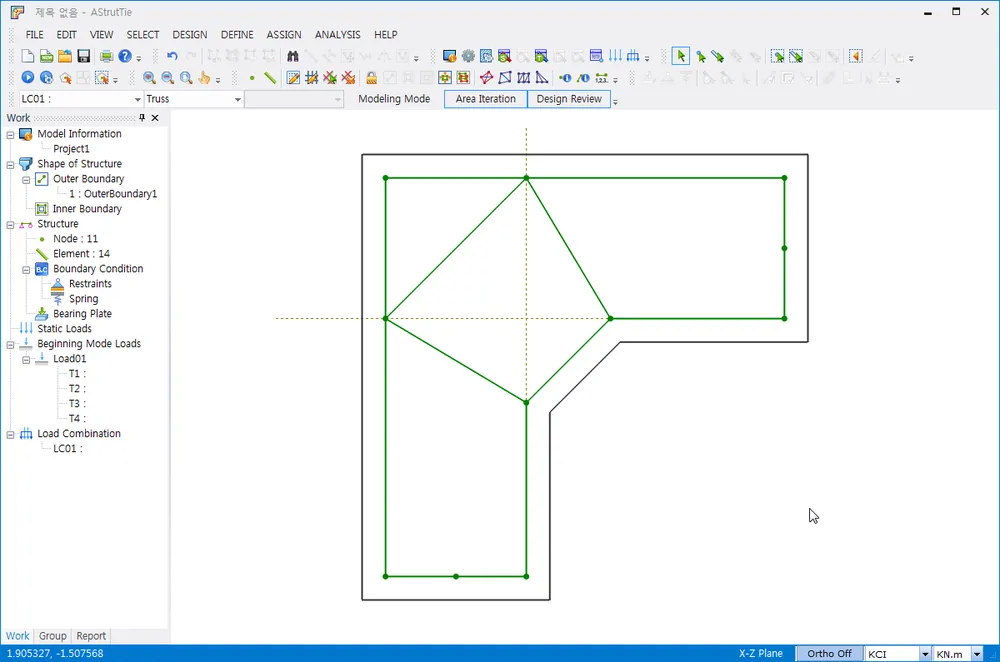
The unnecessary elements of truss model are deleted by using Del Key or Delete functions after selecting the elements.
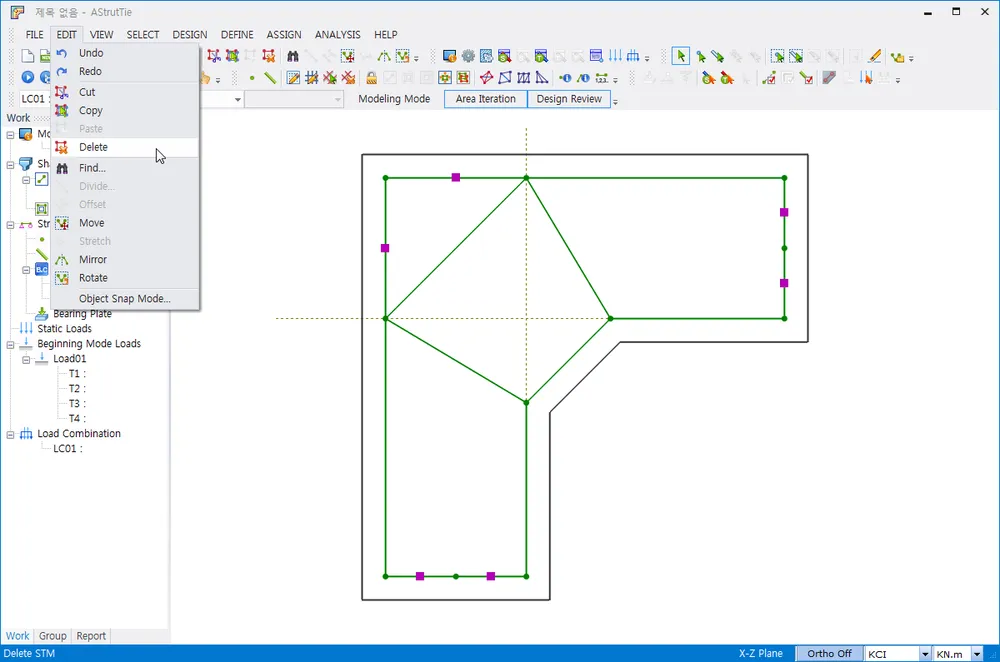
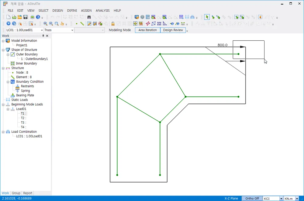
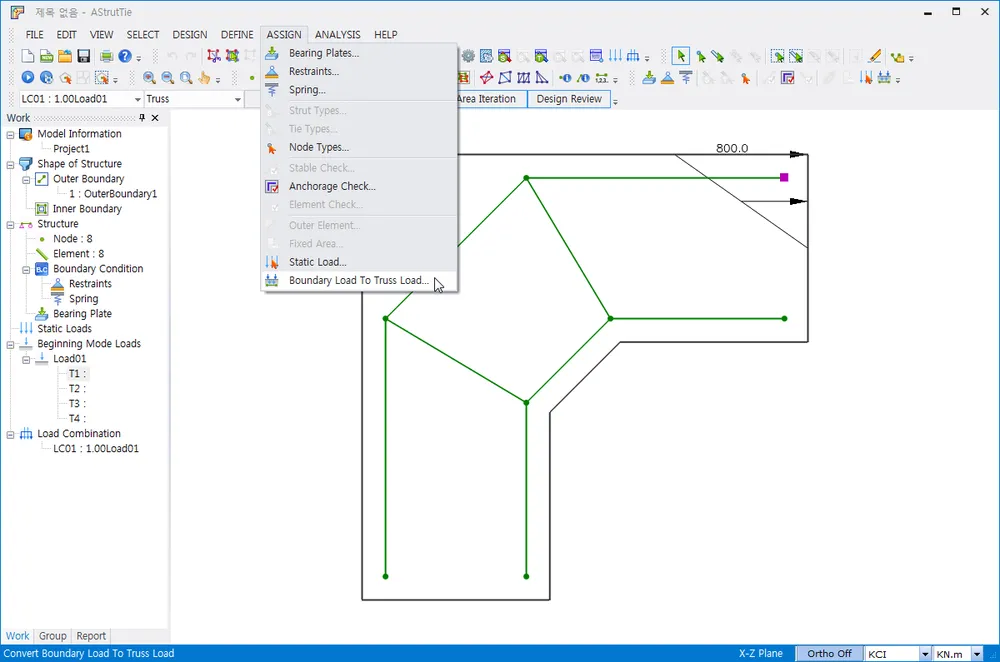
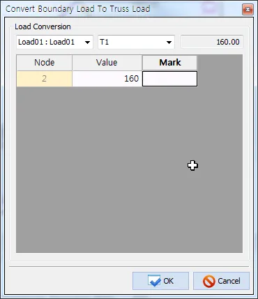
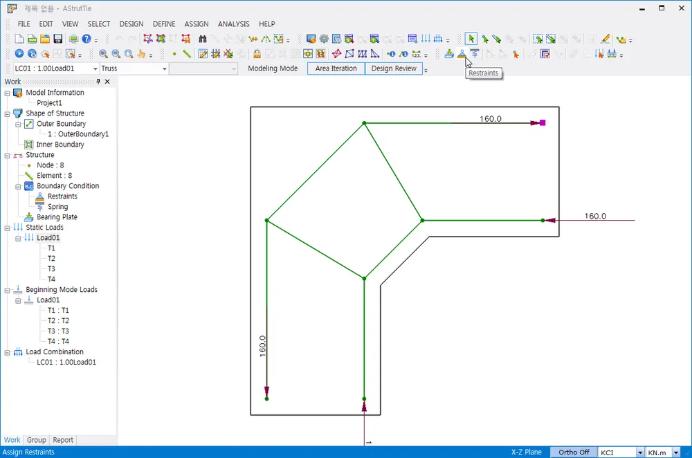
The external loads assigned in the Beginning Mode are converted to the loads acting on the generated truss model by clicking ASSIGN-Boundary Load To Truss Load. The loads on truss model can be input again by designers ’ decision.
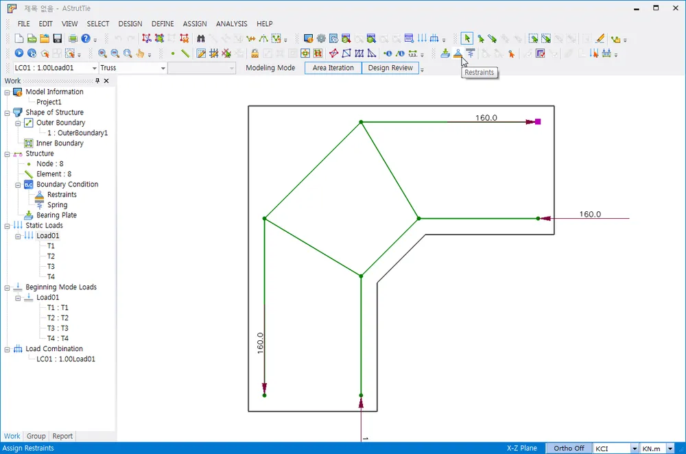
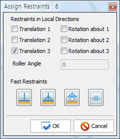
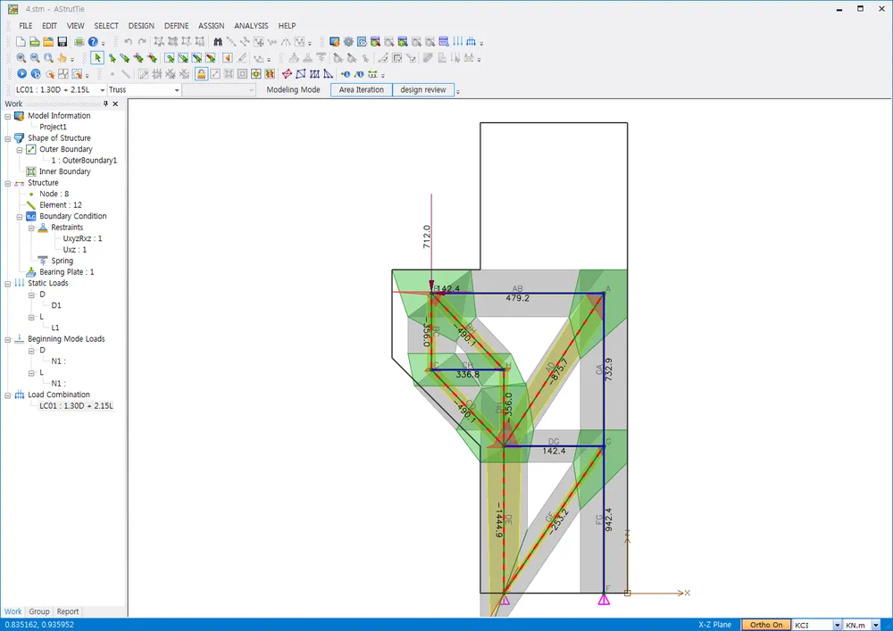
After selecting the nodes on which restraints must be imposed, the boundary conditions are setup by clicking ASSIGN-Restraints. The structural analysis on the truss model is conducted by clicking ANALYSIS-Run Analysis. After the analysis, the results including element forces are shown on the truss model.
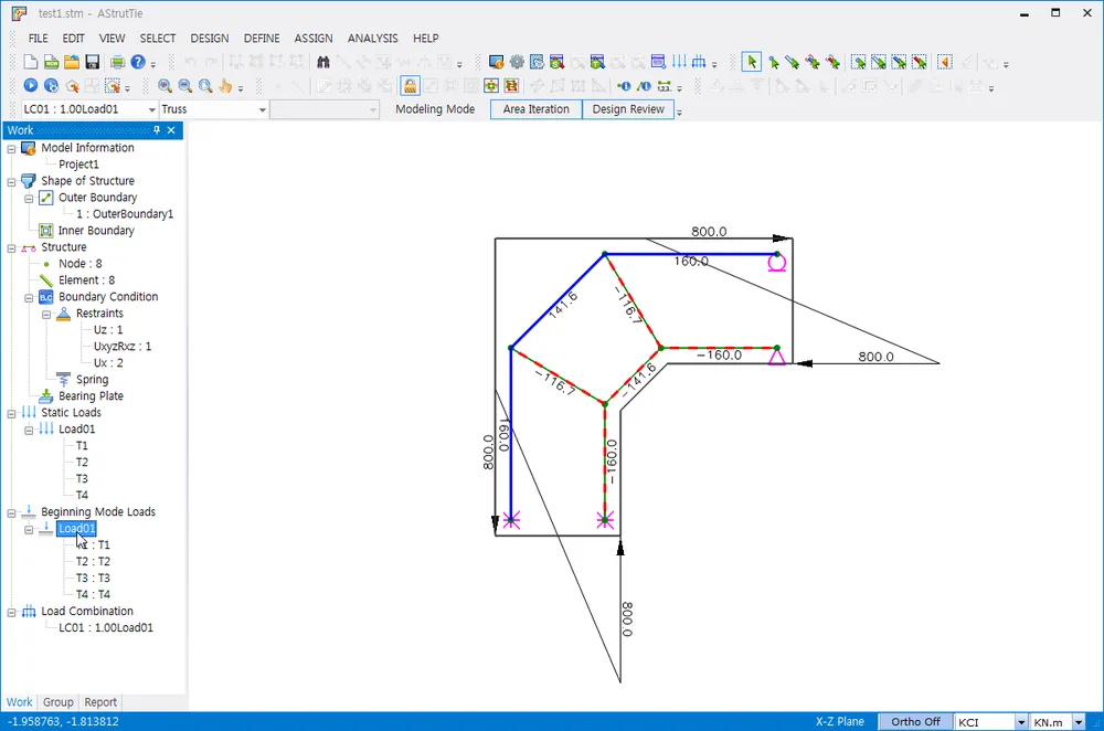
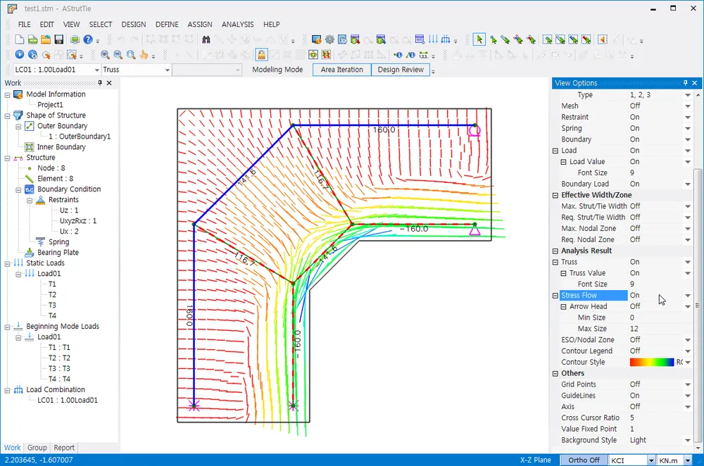
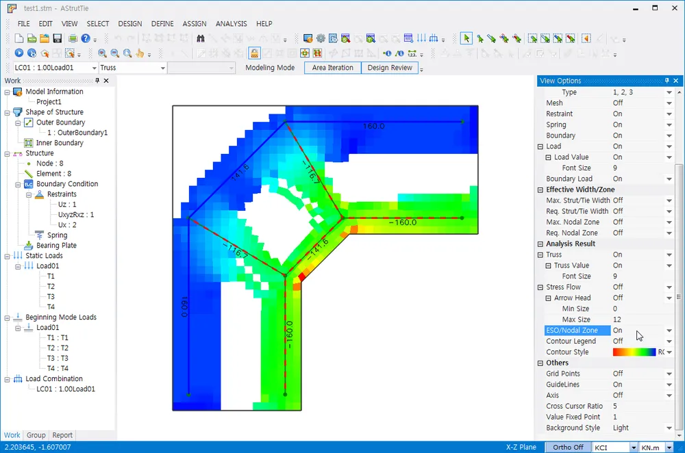
The compressive principal stress flows or the optimization results obtained earlier can be overlapped on the truss model by activating VIEW-View Options, as shown below.
Analysis Results and Structural Design Report
#By clicking Design Review after the structural analysis of the truss model, the information on…
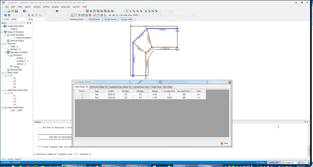
By clicking Design Review after the structural analysis of the truss model, the information on the cross-sectional forces of struts and ties, required and provided reinforcements, minimum reinforcements, and strength verifications of struts and nodal zones is displayed in Truss Design Review window, as shown below.
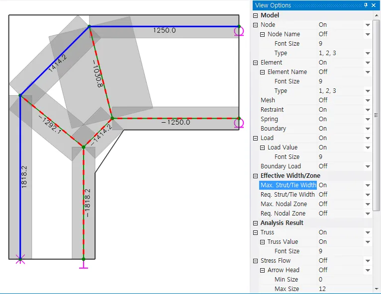
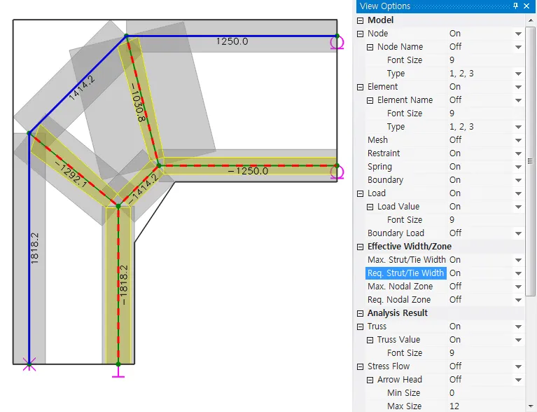
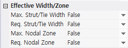
The strength conditions of concrete struts can be verified visually by executing Max. Strut/Tie Width and Req. Strut/Tie Width functions in View Options Window. In the figures shown below, the (grey-colored) maximum widths of tension and compression elements are shown in the left, and the maximum and (yellow-colored) required widths of the elements are shown in the right.
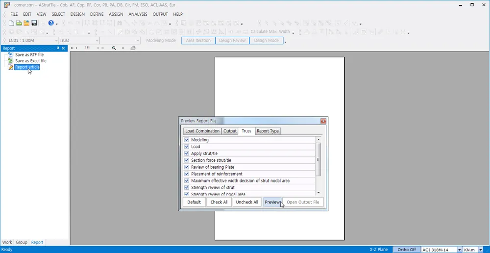
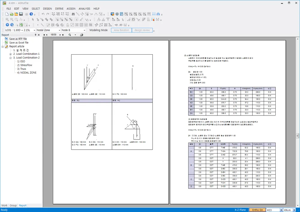
The structural design report can be previewed by double clicking Report article or clicking Preview while the right button of mouse is clicked. The items that must be previewed or printed can be selected , as shown below.
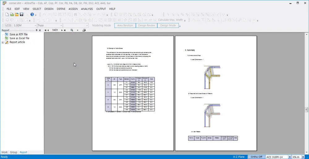
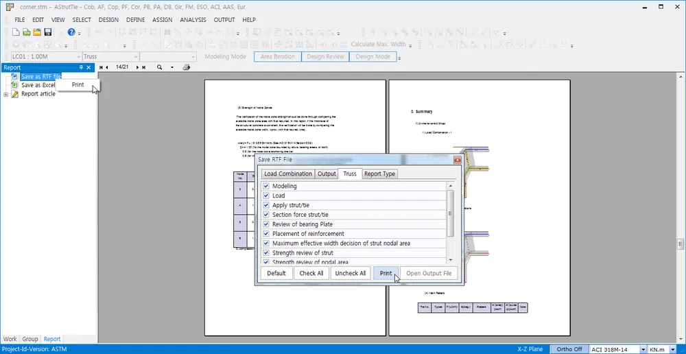
The structural design report is saved (or printed) as a RTF or an Excel file by double clicking Save as RTF file or Save as Excel file in Report Tab. The report is also saved by clicking Print while the right button of mouse is clicked. Note that the report can be saved as an Excel file only if the Microsoft Excel program is installed in the computer.
General Aspects

Outlines
#The AstrutTie consists of 7 windows as shown below.
The AstrutTie consists of 7 windows as shown below.
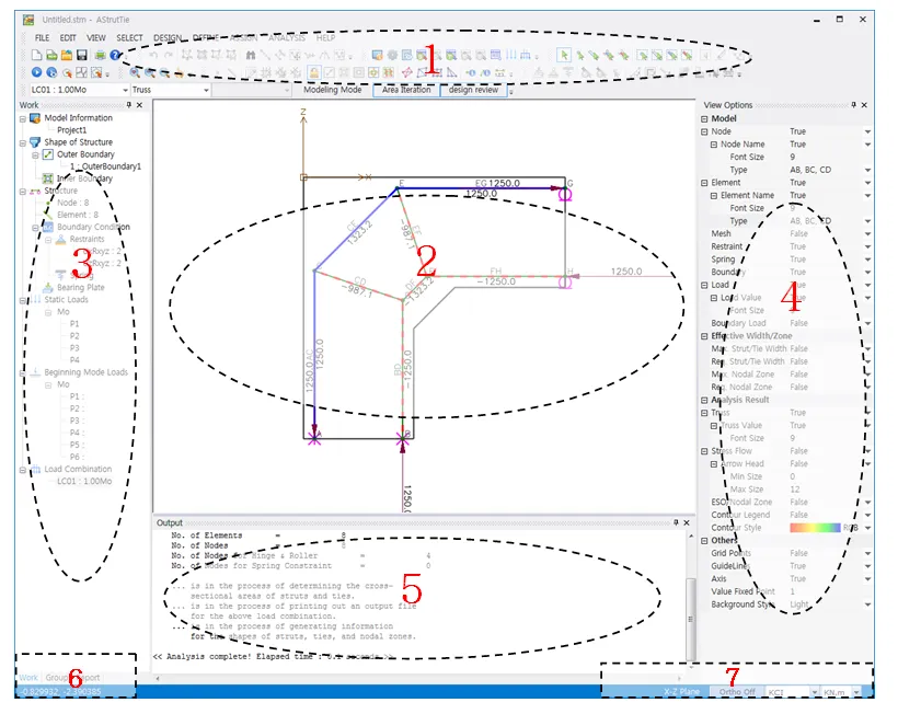
(1) Pull-down Menu & Shortcut Icon Menu Window
Most of the AStrutTie functions can be called in the pull-down menu window. Quick modeling of a concrete member is possible by using shortcut menus of the shortcut icon menu window.
(2) Modeling and Result Display Window
In this window, the finite element models for plane solid and truss structures and their analysis results including compressive principal stress flows, evolutionary structural optimization, and cross-sectional forces of struts and ties are visualized. The structural design report (html, Excel) can be previewed and printed in Report tab.
(3) Tree Menu Window
All types of information on the geometry of concrete member, element and node numbers, boundary and load conditions, and element and node groups are presented in this window. The list of structural design report is also shown.
(4) View Options Window
The view options regarding the finite element models of plane solid and truss structures, structural analysis results, and available widths of strut-tie model elements can be set.
(5) Output Display Window
In this window, the finite element analysis results of plane solid and strut-tie model is displaced in real time.
(6) Tree Menu Tab Window
The transformations of tree menus (Work, Group, Report) are possible.
(7) Design Code & Unit Selection Window
The design code and unit employed in the strut-tie model design are selected in this window.
Pull-down Menu
#This menu includes all kinds of functions for conducting the finite element analysis of plane…
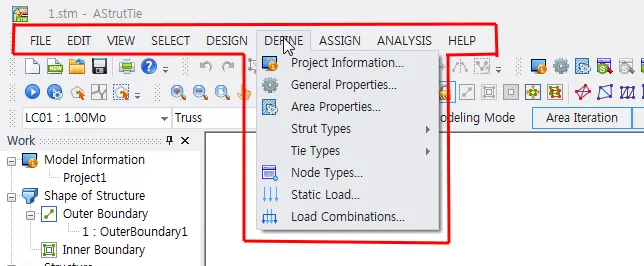
This menu includes all kinds of functions for conducting the finite element analysis of plane solid and plane truss structures required for strut-tie model design of structural members. Detailed functions can be activated by the items FILE, EDIT, VIEW, SELECT, DESIGN, DEFINE, ANALYSIS, and HELP. Each item is explained later.
Shortcut Menu
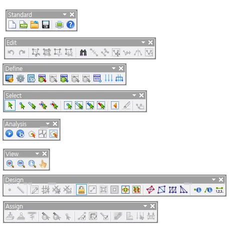
#These icon-type shortcut menus are used to activate main functions quickly. When the mouse is…

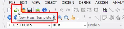
These icon-type shortcut menus are used to activate main functions quickly. When the mouse is close to an icon, a popup message appears.
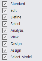
When the right button of mouse is clicked on a shortcut menu, the selection boxes show up.
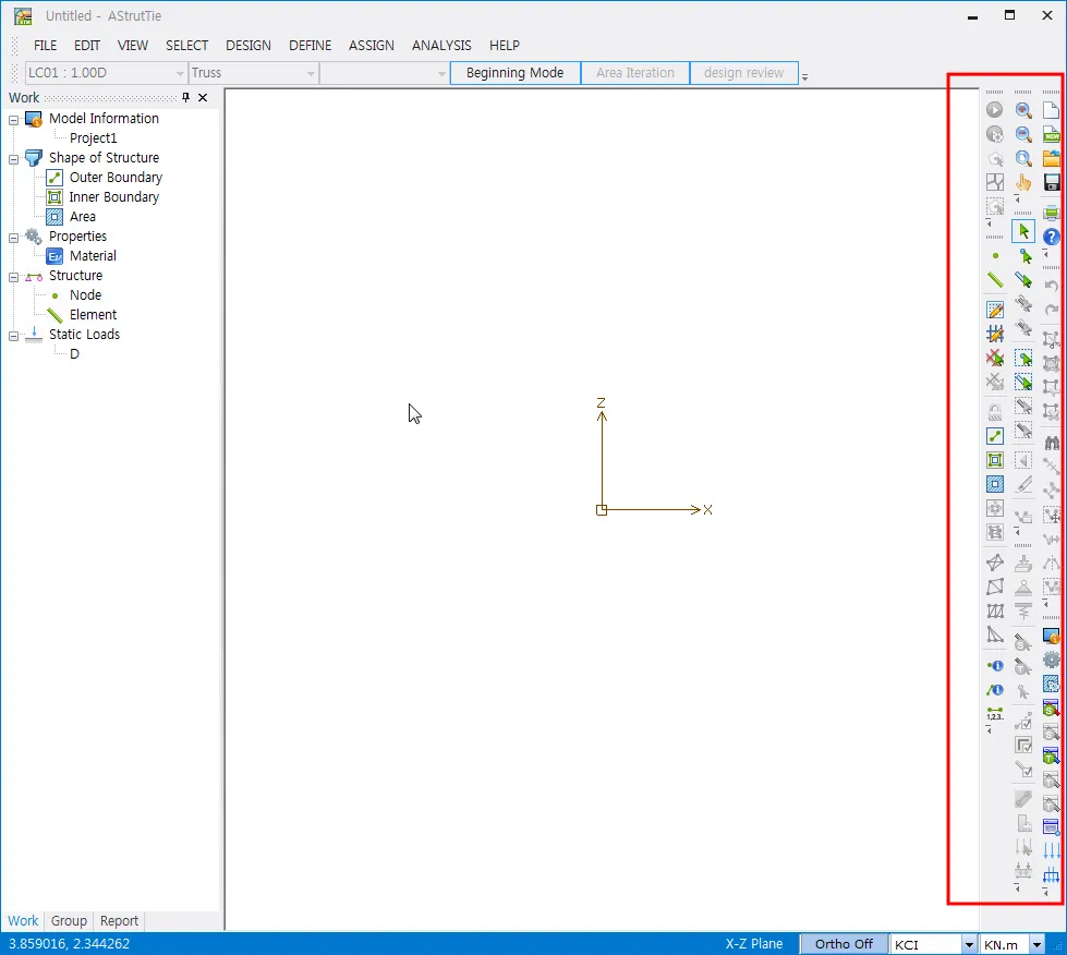
The shortcut icons can be placed separately at other locations. The shortcut menu window can also be lined vertically, as
shown below.
Model Selection Menu
#For a given load combination, a two-dimensional finite element model for evolutionary…
For a given load combination, a two-dimensional finite element model for evolutionary structural optimization, compressive principal stress flows, truss structure, or nodal zone can be selected in the Modeling Mode. This menu does not function in the Beginning Mode.




Optimized Area / Fixed Area
The cross-sectional areas of struts and ties in a strut-tie model are determined by a simple optimization technique when the Optimized Area is selected. When the Fixed Area is picked, the cross-sectional areas of struts and ties must be assigned.

Design Review
After the structural analysis of constructed strut-tie model, the design results regarding the strength verification of struts, ties, and nodal zones can be reviewed.

Design Mode/Analysis Mode
A concrete member is designed by using the strut-tie model method when the Design Mode is clicked. On the other hand, the ultimate strength and behavior of a concrete member are evaluated by the strut-tie model method when the Analysis Mode is selected. In the Analysis Mode, the amount of reinforcement placed in a concrete member must be transformed to the cross-sectional areas of steel ties of strut-tie model.

Modeling View
#The geometrical shape of concrete member, finite element models of plane solid and truss…
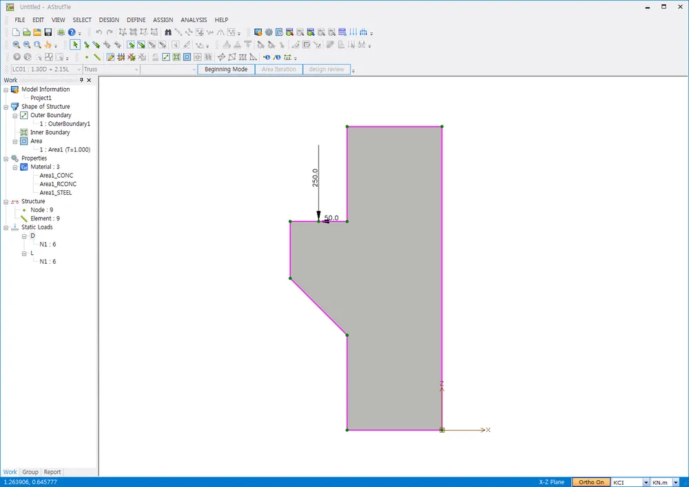
The geometrical shape of concrete member, finite element models of plane solid and truss structures, and structural analysis and design results are visualized. The structural design report can be previewed in Report tab.
1. Beginning Mode
2. Modeling Mode - ESO
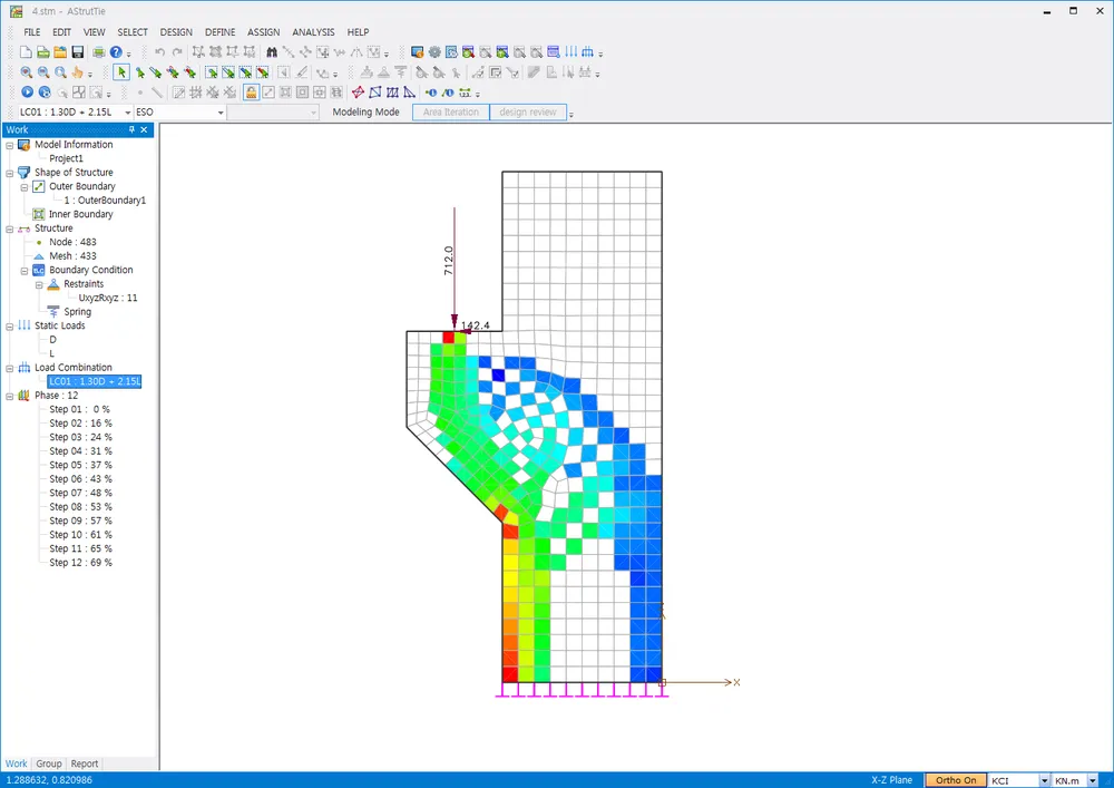
When the ESO analysis is completed, the intermediate steps appear in Menu Tree-Phase. If one of the steps is clicked, the analysis results are visualized in Display Window.
3. Modeling Mode - Stress Flow
4. Modeling Mode - Truss
5. Report
Finite elements and nodes are generated for constructing the finite element model of a concrete member. The intermediate finite element model can be examined by designating the Outer Boundary and Inner Boundary and by applying Area. Some of the notations in the model can (dis)appear by altering the view options in the View Options Window.
The finite elements and nodes captured by mouse can be edited by coping, deleting, and moving. The information on the captured elements and nodes can also be assigned.
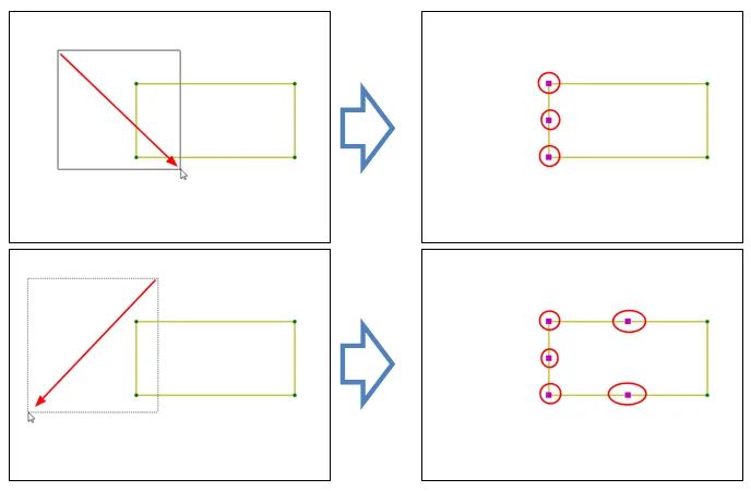
Multiple finite elements and nodes can be selected by dragging the mouse or using [shift + click], as shown below.
Tree Menu

Work
#The operating items related to the mode and modeling are displayed in this menu.
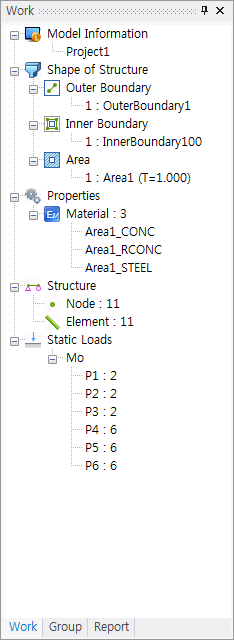
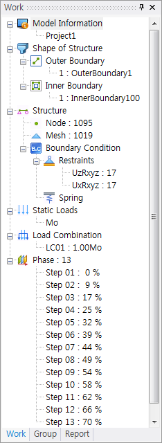
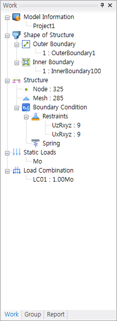
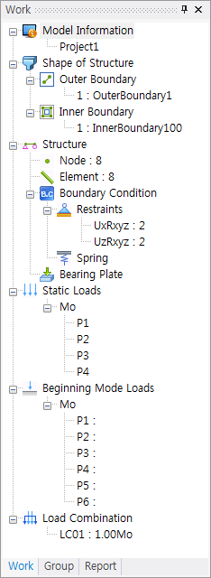
The operating items related to the mode and modeling are displayed in this menu.
Beginning Mode
Modeling Mode - ESO Modeling Mode - Stress Flow
Modeling Mode - Truss
Model Information
The project name is displayed. When the Edit Properties is activated in the ConText menu by double clicking the mouse or clicking the right button of the mouse, the same items as those in the DEFINE-Project Information can be defined.
Structural Shape
The Outer Boundary, Inner Boundary, and Area Type are displayed. In the ConText menu showed up by clicking the right button of the mouse, items can be selected or deselected by the Select/Deselect. In the case of Area Type, when the Edit Properties is activated in the ConText menu by double clicking the mouse or clicking the right button of the mouse, the same items as those in the DEFINE-Area Properties can be defined.
Finite Element Model
Information regarding the number of nodes, number of elements, boundary conditions, and bearing plates is displayed. In the ConText menu showed up by clicking the right button of the mouse, items can be selected or deselected by the Select/Deselect. When the Edit Properties is activated in the ConText menu by double clicking the mouse or clicking the right button of the mouse, the same items as.
Material Properties
The material properties assigned in the Area Type are displayed.
Static Loads
The load types are displayed. If a certain load type is clicked, the load of the load type imposed on a finite element model is showed up in the Modeling and Result Display Window.
Load Combinations
The load combinations are displayed. If a certain load combination is clicked, the loads of the load combination implemented with load factors are showed up in the Modeling and Result Display Window.
Loads in Beginning Mode
The load types assigned in the Modeling Mode-Truss are displayed. If a certain load type is selected, the loads of the load type are showed up in the Modeling and Result Display Window.
Analysis Phase
The finite element analysis steps illustrating the elimination percentage of finite elements in ESO are displayed. If a certain step is clicked, the optimization results of the step are showed up in the Modeling and Result Display Window.
Group
#The information regarding the grouping of nodes and elements are displayed by clicking Group in…
The information regarding the grouping of nodes and elements are displayed by clicking Group in the Tree Menu Tab Window. The nodes or elements grouped in the SELECT Menu can be selected and edited. The nodes and/or elements can be added or deleted by reselecting them in the Modeling and Result Display Window.
Report
#The structural design report can be previewed by clicking the Report in the Tree Menu Tab…
The structural design report can be previewed by clicking the Report in the Tree Menu Tab Window. The printing options can be selected in the ANALYSIS-Analysis & Printing Options.
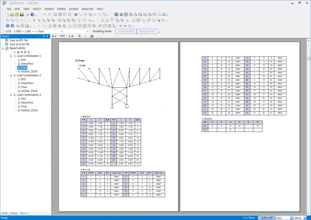
Detail of Pull-down Menu

FILE
#New
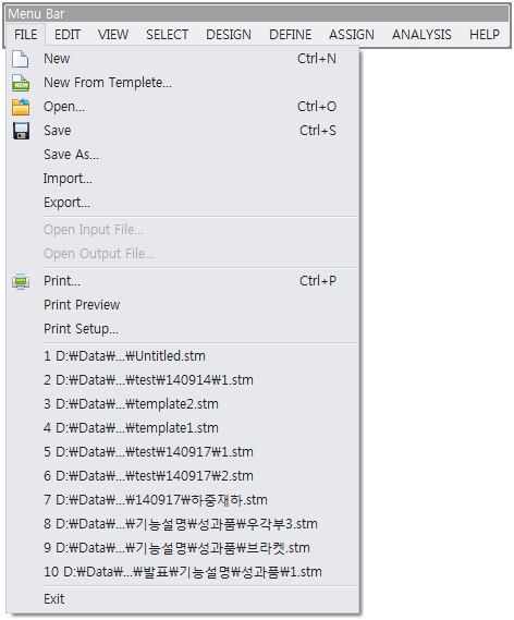
New
A new file is generated by using the function New. Caution is needed since the data that are not saved can be deleted by using this function.
New From Template...
A new file basing a Template is generated by this function. Caution is needed since the data that are not saved can be deleted by using this function. Details on Template are introduced later. The function is activated only in Template module.
Open...
A previously saved file named as *.stm is opened by this function. Caution is needed since the data that are not saved can be deleted by using this function. A *.stm file generated by other program (module) can also be opened. The functions regarding the structural analysis of strut-tie model and printout of structural design report are not supported for the file generated by other program.
Save
An existing or new working file is saved with the filename extension *.stm in the program AStrutTie.
Save As...
An existing or new working file is saved as other filename with the filename extension *.stm.
Import...
A drawing file saved as Dxf type is imported by this function. Caution is needed since the data that are not saved can be deleted by using this function. The function is activated only in Free Modeling module.
Export...
The finite element models for plane solid and truss structures are exported as Dxf type drawing files. The function is activated only in Free Modeling module.
View Input File...
The input file of the currently working model is opened as a text-editor, and the contents of the input file can be checked.
View Output File...
The output file of the currently working model can be opened as a text-editor, and the contents of the output file can be examined.
Recently Worked File
The previous 10 projects are listed. A project is opened by clicking one of them.
Exit
The AStrutTie is terminated by this function.
EDIT
#Undo
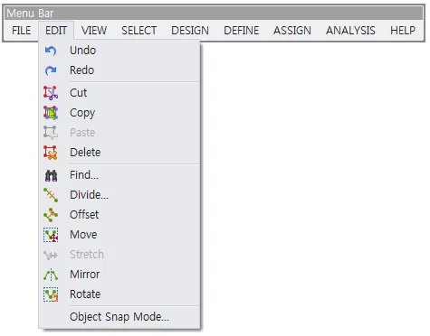
Undo
The previous work is cancelled by this function. The previous works are cancelled step by step by applying the Undo function repeatedly. Once the structural analysis, mode change, load combination change, or modeling change has been completed, the Undo function does not activate on the previous actions. The previous work can also be cancelled by the shortcut key [ctrl + z].
Redo
The work cancelled by the Undo function is reinstated by this function. The previous works cancelled step by step by the Undo function are reinstated by applying the Redo function repeatedly. Once the structural analysis, mode change, load combination change, or modeling change has been completed, the Redo function does not fulfill its function. The previous work can also be reinstated by the shortcut key [ctrl + r].
Cut
The components of finite element model such as finite elements and nodes are cut and saved in the clipboard by this function. The contents saved previously in the clipboard are deleted. The function is also activated by the shortcut key [ctrl + x].
Copy
The components of finite element model are copied and saved in the clipboard by this function. The contents saved previously in the clipboard are deleted. The function is also activated by the shortcut key [ctrl + c].
Paste
The contents saved in the clipboard by the function Cut or Copy are called and pasted by this function. When pasting, a reference point must be designated by clicking the mouse or inputting the coordinates of the reference point. The reference point must be located at the smallest values of x- and z-coordinate of the contents. The function can also be activated by the shortcut key [ctrl + v].
Delete
The components of finite element model are deleted by this function. The information assigned to each component is also deleted. The function of this function can also be activated by the key [Delete].
Find...
The components of finite element model are searched by this function. A node or finite element is found by typing in a number or character in View Options Window.
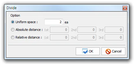
Divide...
A selected element in the finite element model of truss structure is divided into multiple elements according to the following three options.
Uniform space: An element is divided into multiple equal-sized elements by typing in the desired number of elements.
Absolute distance: An element is divided into multiple equal- or unequal-sized elements by assigning reference point(s). The number of reference points and generated elements cannot exceed 3 and 4, respectively.
Relative distance: An element is divided into multiple equal- or unequal-sized elements by typing in the size ratio(s) ranging 0 to 1. The size ratio is the length ratio of the generated element to the original element. The number of size ratios and generated elements cannot exceed 3 and 4, respectively.
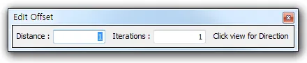
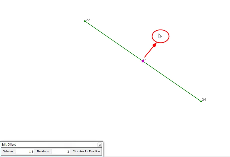
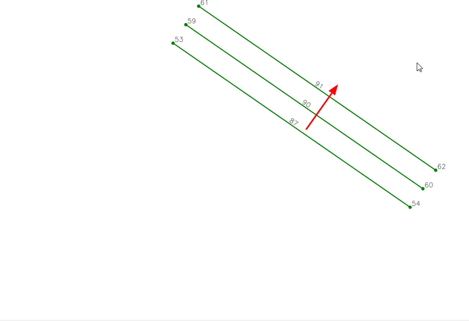
Offset...
A new element that is parallel to the selected element is generated by this function. The distance between the selected element and the newly generated element must be assigned along with the number of elements that must be generated.
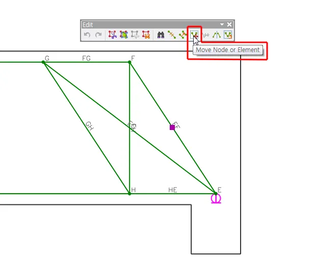
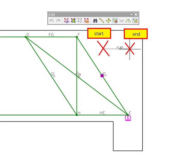
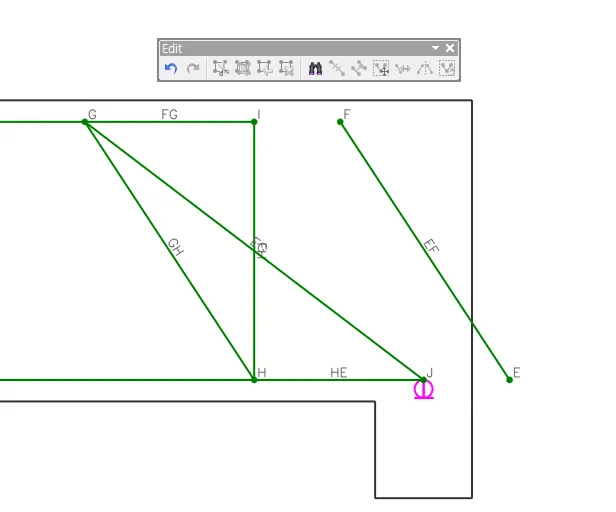
Move...
The location of a selected element is altered by this function. The reference and moving points must be assigned by clicking the mouse.
https://youtu.be/N-S5X3oIgws
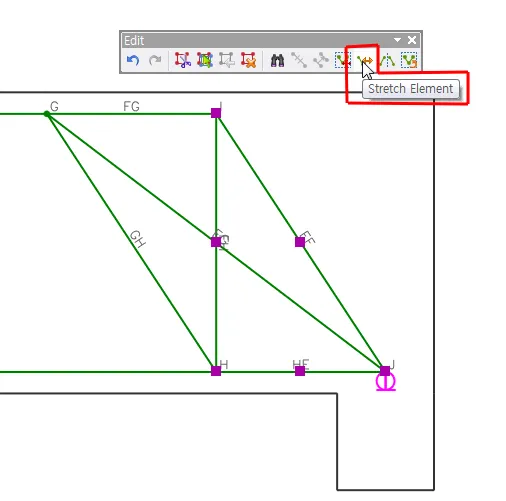
Stretch
The lengths of elements that are connected to some selected elements are changed by moving the selected elements and nodes. The reference and moving points must be assigned by clicking the mouse. Without using the Pull-down menu and shortcut key, the positions of nodes can be moved directly by the mouse.
https://youtu.be/WVaXFBMOm60
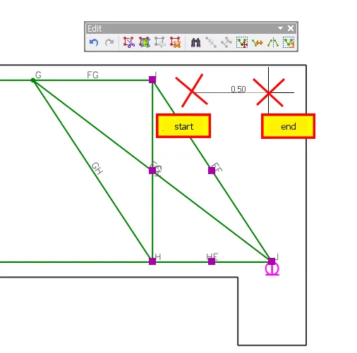
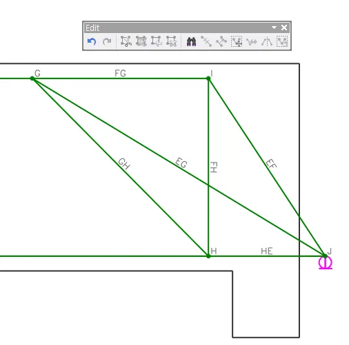
Mirror
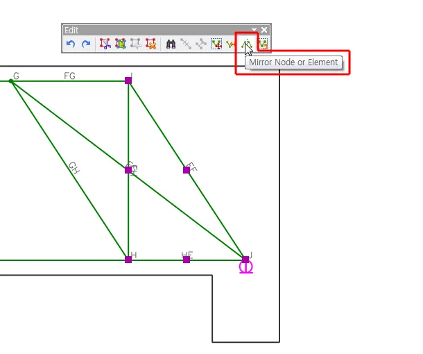
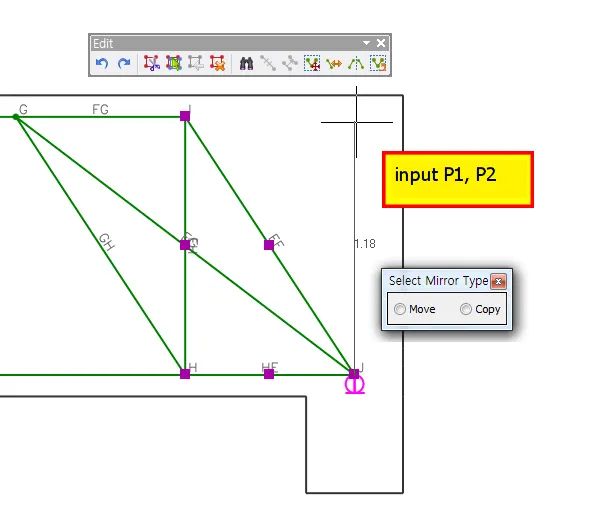
The selected elements and nodes are copied and moved symmetrically by this function. Prior to selecting the mirror type Move or Copy, a reference line must be determined by clicking the mouse twice.
https://youtu.be/MacETCnSldE
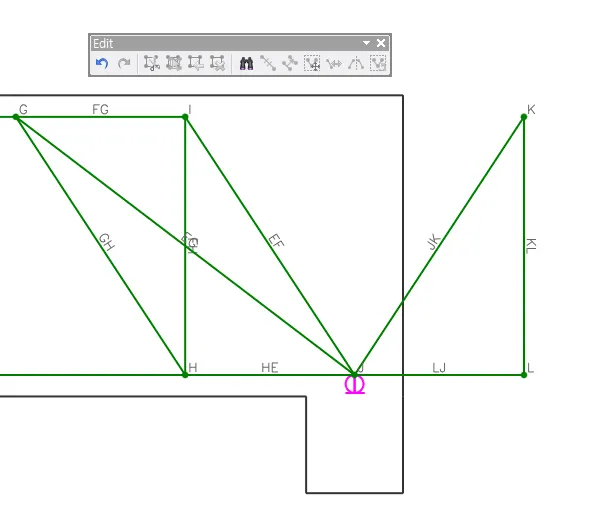
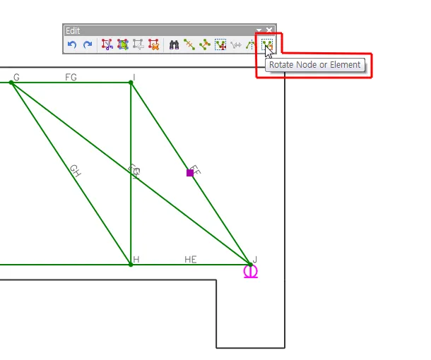
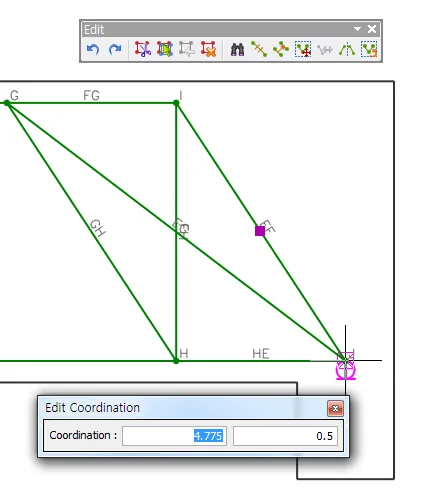
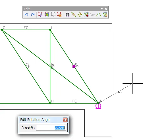
Rotate
A selected element is rotated by this function. A reference point and rotating angle must be assigned in order.
https://youtu.be/AbC_IERlLPU
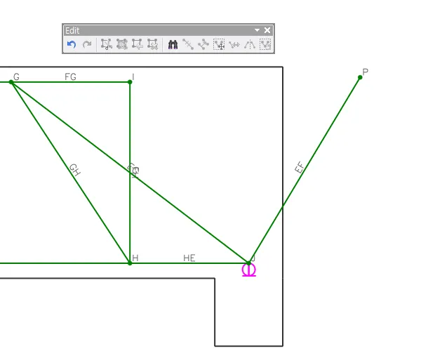
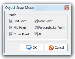
Object Snap Mode
The snaps helpful for the modeling and editing of truss structure can be set by this function.
Edit Template
This function is working only for the models constructed by using a Template. The editing works regarding the changes or refinements of geometrical shape of concrete member, load and boundary conditions, and truss model are possible by this function. These Menus are same of New form Template Dialog.
VIEW
#The functions for (de)activating the sub windows (or menus) in the Tree Menu Window are…
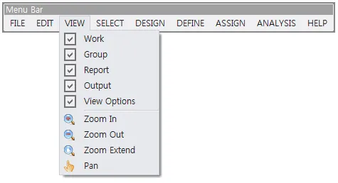
The functions for (de)activating the sub windows (or menus) in the Tree Menu Window are provided. The functions for adjusting the views in Modeling and Result Display Window are also provided.
Work
The sub window Work in the Tree Menu Window is (de)activated by this function.
Group
The sub window Group in the Tree Menu Window is (de)activated.
Report
The sub window Report in the Tree Menu Window is (de)activated.
Output
The Output Display Window is (de)activated.
View Options
The View Options Window is (de)activated.
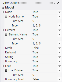
Model
The information on the finite element models for plane solid and truss structures is or is not displayed with variable font sizes and designation methods by clicking True or False in the View Options Window - Model.
Effective Width/Zone
The available and required widths of struts, ties, and nodal zones are or are not displayed by clicking True or False in the View Options Window – Effective Width/Zone.
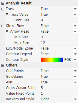
Analysis Result
The finite element analysis results including the cross-sectional forces of truss elements, compressive principal stress flows of a concrete member, ESO, and nodal zones are or are not displayed by clicking True or False in the View Options Window – Analysis Result.
Zoom In
The Modeling and Result Display Window is enlarged from the mouse cursor by scrolling the mouse wheel up.
Zoom Out
The Modeling and Result Display Window is reduced from the mouse cursor by scrolling the mouse wheel down.
Zoom Extend
The Modeling and Result Display Window is enlarged or reduced automatically to show all the concrete members and corresponding models. This function is also activated by clicking the mouse wheel button twice.
Pan
The Modeling and Result Display Window is shifted by dragging the mouse while clicked. The window can also be shifted by the mouse wheel button.
SELECT
#Any
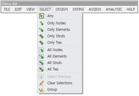
Any
Either of elements, nodes, struts, or ties is selected by this function
Only Nodes
The nodes in a finite element model are selected only.
Only Elements
The elements in a finite element model are selected only.
Only Struts
The struts in the strut-tie model of a concrete member are selected only. When this function is activated, the function Only Ties cannot be activated. This function is activated after conducting a finite element analysis of truss structure.
Only Ties
The ties in the strut-tie model of a concrete member are selected only. When this function is activated, the function Only Struts cannot be activated. This function is activated after conducting a finite element analysis of truss structure.
All Nodes
All the nodes in a finite element model are selected.
All Elements
All the elements in a finite element model are selected.
All Struts
All the struts in the strut-tie model of a concrete member are selected. This function is activated after conducting a finite element analysis of truss structure.
All Ties
All the ties in the strut-tie model of a concrete member are selected. This function is activated after conducting a finite element analysis of truss structure.
Select Previous
The elements and nodes selected previously are reselected during the operation of EDIT or ASSIGN.
Clear Selections
All the selections are cancelled. The selections can also be cancelled by clicking a vacant spot of Modeling and Result Display Window.
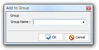
Group
The selected elements and nodes are designated as a group.
DESIGN
#Add Nodes
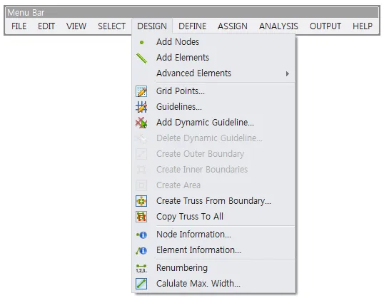
Add Nodes
Finite element nodes for constructing the finite element models of plane solid and truss structures are generated by this function. The generated nodes must be connected to their corresponding finite element(s). This function is used in the Beginning Mode and Modeling Mode – Truss.
Add Elements
A finite element is generated by assigning the coordinates of both end points of the element. More elements are generated by using this function repeatedly. This function is used in the Beginning Mode and Modeling Mode – Truss.
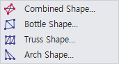
Advanced Elements
Four types of truss element sets shown below are provided to construct a finite element model of truss structure quickly and efficiently. This function is used in the Modeling Mode – Truss and Free Modeling module.
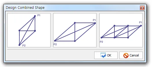
Design Combined Shape
To activate this function, two points, P1 and P2, in the combined shapes shown below must be clicked after selecting one of the combined shapes. The shape of the element set does not change regardless of the clicking order of the two points.
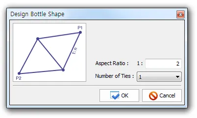
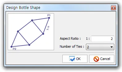
Design Bottle Shape
A bottle-shaped element set is generated by this function. To activate this function, two points, P1 and P2, in the bottle shapes shown below must be clicked after selecting one of the bottle shapes. The aspect ratio to determine the slopes of inclined elements and the number of ties limited to 2 must be assigned.
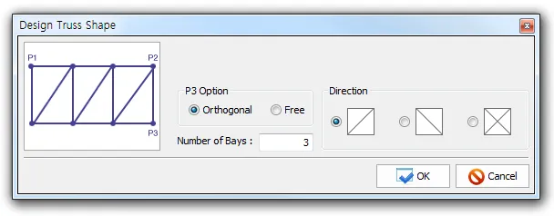
Design Truss Shape
A rectangular-shaped element set is generated by this function. To activate this function, three points (P1, P2, P3) as shown below must be assigned. The direction of inclined element is changed according to the input order of the points. The rectangular-shaped element set is transformed to a trapezoid shape if the Free is selected as the P3 Option. The number of bays must be inserted.
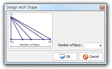
Design Arch Shape
An arch-shaped element set is generated by this function. To activate this function, three points (P1, P2, P3) as shown below must be assigned. The direction of inclined element is changed according to the input order of the points. The number of bays must be inserted.
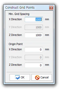
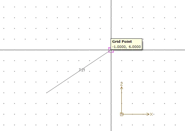
Grid Points...
The numerous points visualizing multiple grid lines as shown below are generated in the Modeling and Result Display Window by this function. The grid lines can be helpful for constructing the geometrical shape of concrete member and the finite element models of plane solid and truss structures. This function is activated by setting the Grid Points to True in the View Options Window. The minimum grid spacing and the coordinates of origin point must be assigned.
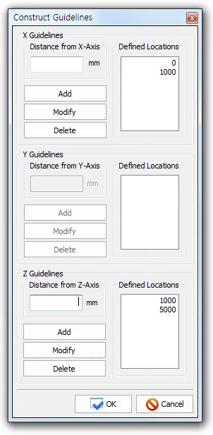
Guidelines...
The guidelines as shown below are generated in the Modeling and Result Display Window by this function. The guidelines can be helpful for constructing the geometrical shape of concrete member and the finite element models of plane solid and truss structures. This function is activated by setting the Guidelines to True in the View Options Window. Horizontal and vertical guidelines are generated by assigning the distances from the orthogonal axes. The guidelines can be added/modified/deleted by changing the assigned distances.
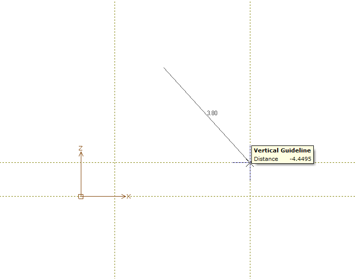
Add Dynamic Guideline
It make easy guideline. User define guideline.
https://youtu.be/-5u9Xe77iH8
Delete Dynamic Guideline
Create Outer Boundary
The outer boundary of a concrete member is generated by this function. The function is applicable only in the Beginning Mode. It is not activated when the every boundary line shaping a concrete member is not connected completely. The outer boundary is created only once. If another outer boundary is created, the previous outer boundary is deleted.
Create Inner Boundaries
The inner boundaries for modeling the openings of a concrete member are generated by this function. The function is applicable only in the Beginning Mode. It is not activated when the every boundary line shaping an opening is not connected completely. The function must be activated after creating the outer boundary of a concrete member. The openings must be positioned inside of the outer boundary. Multiple inner boundaries can be created.
Create Area
The area of a concrete member surrounded by its outer boundary is generated by this function. This function is applicable only in the Beginning Mode.
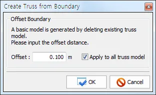
Create Truss From Boundary
Truss elements for a concrete member, with a certain distance away from its outer and inner boundaries , are created automatically by this function. The distance, considered as one-half of the available widths of the truss elements, must be assigned.
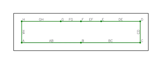
Copy Truss To All
A truss model for a given load combination can be copied to those of all load combinations by this function. Caution is needed because the previous truss models for other load combinations are all deleted once the function is activated.
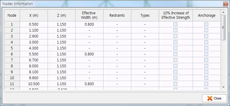
Node Information
The information on the nodes of truss model (strut-tie model) is displayed by this function. The information includes the coordinates of node, width of bearing plate, boundary conditions, node type, and anchorage of reinforcing bars. The information on the coordinates and effective strength of node can be modified by this function.
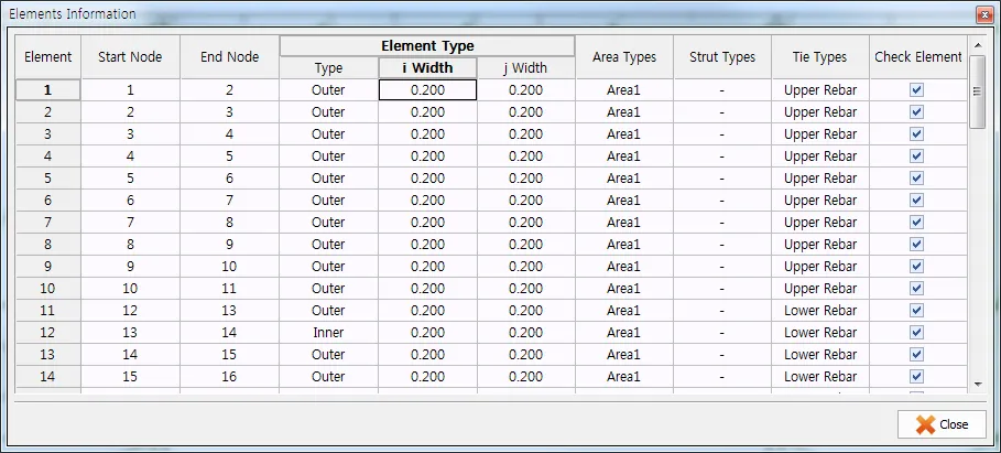
Element Information
The information on the elements of truss model (strut-tie model) is displayed by this function. The information includes the node numbers at element’s both ends (start node, end node), assumed available widths at element’s both ends (i-width, j-width), area type, and tie type. The information on the assumed available widths can be modified by this function.
Renumbering
The element and node numbers (of the finite element models of plane solid and truss structures) that are not in sequential order due to editing of the finite element models are renumbered by this function. The renumbering is activated automatically in the finite element analyses.
Cal. Max Width
The available widths of all elements in a strut-tie model, calculated automatically by the program, are displayed by executing the function DESIGN-Element Information or ASSIGN-Outer Element. The available widths can be modified.
DEFINE
#Project Information...
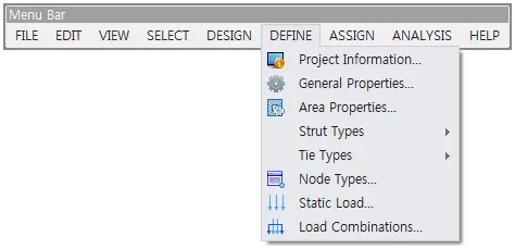
Project Information...
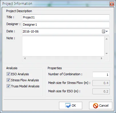
The necessary information that must be included in the structural design report including the types of structural analyses (ESO, Stress Flow, Truss), number of load combinations, and mesh sizes for stress flow and ESO analyses are set here. Caution is needed: when a check mark in the analysis box is removed, the corresponding previous modeling information will be deleted.
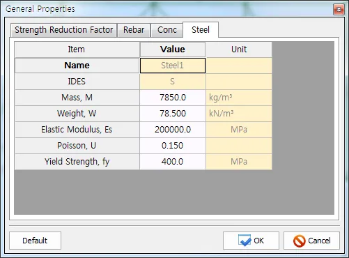
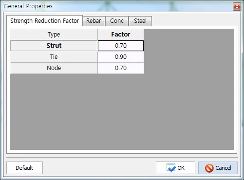
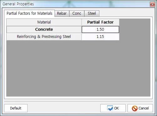
General Properties...
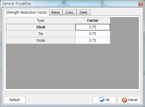
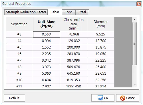
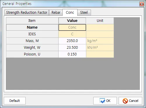
The strength reduction factors of strut, tie, and node are assigned here. The sectional and material properties of reinforcing bars and concrete are also assigned.
ACI 318M-14 (2014)
AASHTO LRFD (2014)
EuroCode 2 (2004)
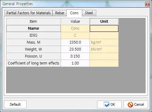
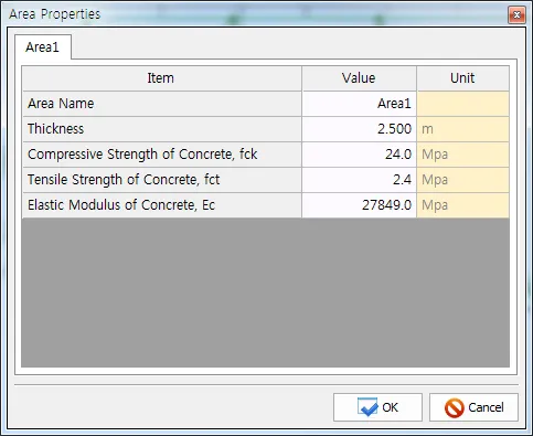
Area Properties...
The thickness and material properties of a concrete member are assigned here.
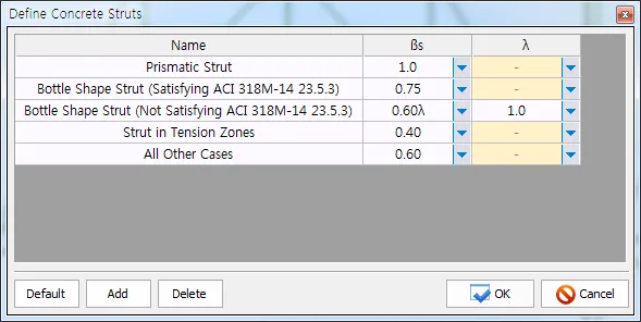
Strut Types
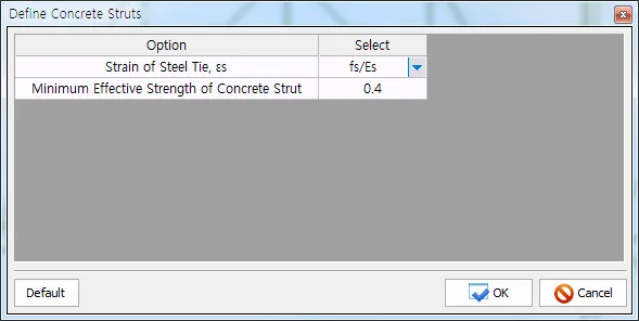
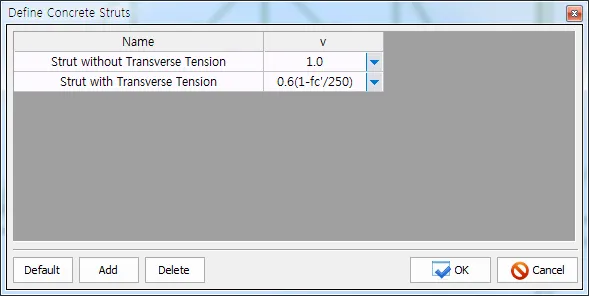
Default types of concrete struts in a strut-tie model are defined here. More strut types can be added.
ACI318M-14 (2014)
AASHTO LRFD (2014)
EuroCode2 (2004)
Tie Types
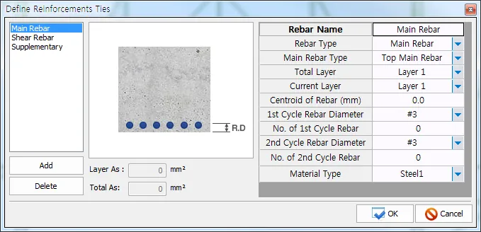
The steel ties in a strut-tie model represent the main reinforcing bars, shear reinforcing bars, and supplementary reinforcing bars of a concrete member. Two different types of reinforcing bars in a horizontal layer and up to 4 vertical layers .
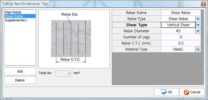
The shear reinforcing bars can be divided into horizontal, vertical, and inclined reinforcing bars. The information on the shear reinforcing bars is required.
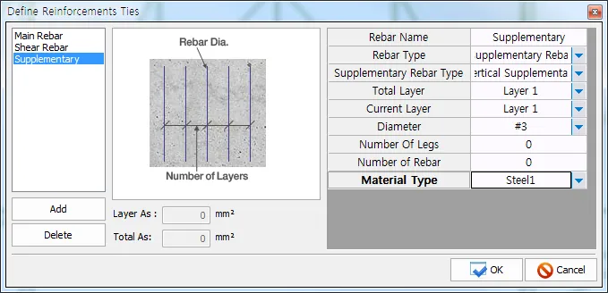
For the horizontal or vertical supplementary reinforcing bars, the number of legs and layers must be assigned.
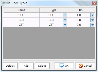
Node Types...
Three types of nodes in a strut-tie model are defined here. More node types can be added.
Static Load...
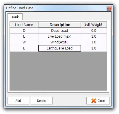
Default types of loads are defined here. More load types can be added.
Load Combinations...
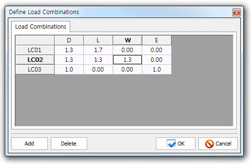
The load combinations that must be considered in the strut-tie model design are defined here. More load combinations can be added. Although the number of load combinations can be changed in the DEFINE-Project Information, it can also be changed here by adding or deleting the combinations. Caution is needed because the information on the finite element models related to a certain load combination is removed when the load combination is deleted.
ASSIGN
#Bearing Plates ...
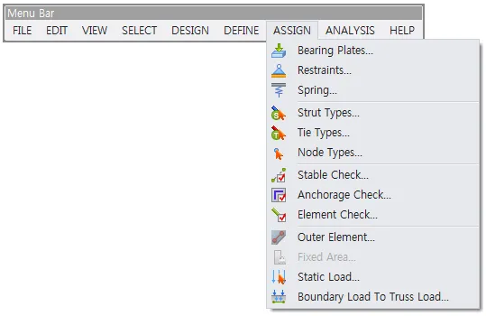
Bearing Plates ...
The specification of bearing plates for bridges or prestressed concrete members is assigned by this function. If the effective width of a bearing plate is typed in, it will be used in calculating the available width of strut and verifying the bearing strength of concrete.
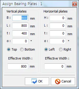
The vertical and horizontal plates support vertical and horizontal loads respectively. In the vertical plate, B, L, t, and are the width, longitudinal length, thickness, and slope (degree) measured from positive horizontal axis, respectively. If the plate is placed on top or bottom of a concrete member, Top or Bottom must be selected. In the horizontal plate, H, L, t, and are the height, longitudinal length, and thickness, and slope (degree) measured from … respectively. If the plate is placed at left or right of a concrete member, Left or Right must be selected.
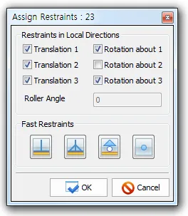
Restraints...
The hinge or roller boundary conditions for the finite element analyses of plane solid and truss structures are assigned by this function.
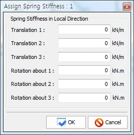
Spring...
The stiffness values of springs in all directions are assigned to the elements modeling spring boundary conditions.
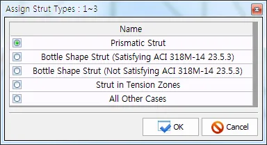
Strut Types...
The types of concrete struts defined earlier by DEFINE-Strut Types-Concrete Struts are assigned to the every element of a strut-tie model after clicking concrete struts one by one.
.
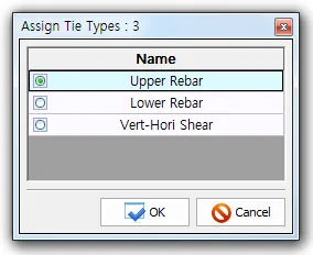
Tie Types...
The types of steel ties defined earlier are assigned to the every element of a strut-tie model. After conducting a finite element analysis of strut-tie model, the elements with tensile cross-sectional forces must be recognized as the steel ties.
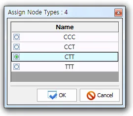
Node Types...
The types of nodes defined earlier are assigned automatically to the every node of a strut-tie model.
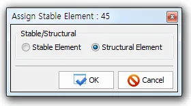
Stability Check...
A constructed strut-tie model can be unstable during the finite element analysis. For this case, the element(s) with very small axial stiffness value(s) can be added to the constructed strut-tie model.
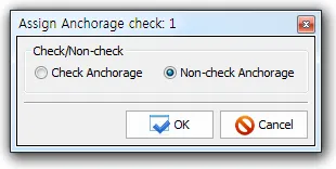
Anchorage Check...
The nodes at which the re-bar anchorage verification is required are assigned by this function.
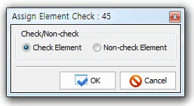
Element Check...
The elements whose strength verifications are not required can be assigned by this function.
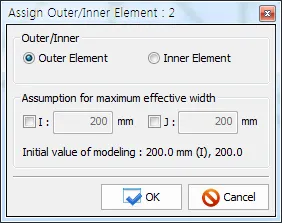
Outer Element...
The boundary elements in a strut-tie model are assigned to the Outer Elements with available widths at elements ’ both ends. The available widths at both ends must be assigned, too. The assigned available widths are used for determining the available widths of other elements.
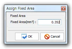
Fixed Area...
The cross-sectional areas of certain elements can be fixed in the iterative process for determining the cross-sectional areas and forces of struts and ties.
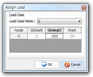
Static Load ...
The external loads in a strut-tie model are imposed by this function. Please refer to Quick Start-Application of Load.
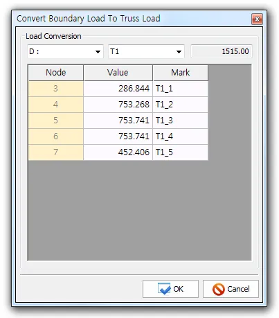
Boundary Load To Truss Load...
The loads imposed to the finite element model of plane solid structure in the Beginning Mode are converted to the loads acting on the nodes of a corresponding strut-tie model. To activate this command, the elements and nodes of the strut-tie model must be selected first. The converted loads can be modified if necessary.
ANALYSIS
#Run Analysis

Run Analysis
The executive files for the finite element analyses for ESO, Stress Flow, Truss, and Nodal Zone are activated by this command. During the execution, nothing can be inputted.
Anlysis & Print Options ...
The problem type, peak strain of concrete and number of incremental load steps for the finite element material nonlinear analysis of a nodal zone, elimination ratio for the evolutionary structural optimization of a concrete member, and maximum memory for finite element analysis are set by this function. The printing options including the convergence ratio in the iterative finite element analysis of a strut-tie model for determining the cross-sectional areas of struts and ties are set, too. More structural analysis time is required with larger incremental load steps or smaller elimination ratio.
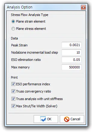
OUTPUT
#Save as Word file...

Save as Word file...
An output file is saved as a Word file (*.rtf) .
Save as Excel file...
An output file is saved as an Excel file (*.xlsx) .
HELP
#Online Manual...
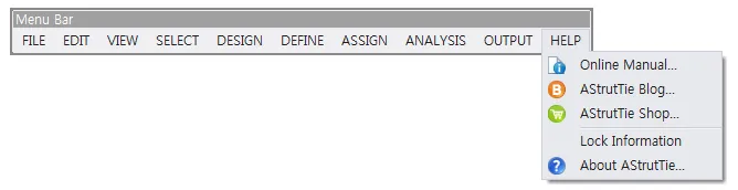
Online Manual...
The online manual of the AStrutTie is provided.
AStrutTie Blog...
The AStrutTie Blog webpage is connedted .
https://www.astruttie.com/ko
AStrutTie Shop...
The AStrutTie Shop webpage is connected.
https://service.aroad.co.kr/shop/astruttie/buy.do
About AStrutTie...
The information on the AStrutTie is provided.
Detail of New from Templates

Corbel
#Dimension
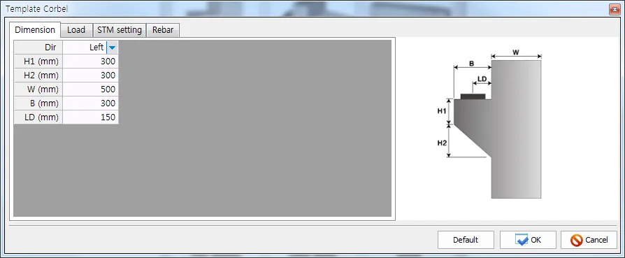
Dimension
The dimensions of a bracket are assigned. The boundary lines of the bracket are drawn according to the assigned dimensions. The loads and the area of reinforcing bars must be converted to those of the bracket with 1 meter thickness since the thickness of the bracket is assumed to be 1 meter.
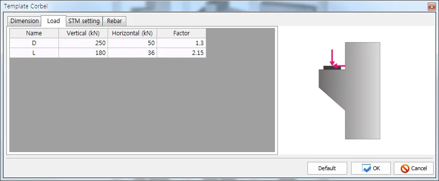
Load
The dead and live loads with their load factors are assigned. After assigning the load names and load factors, they can be altered, added, or deleted in the DEFINE-Static Load. The positive values for vertical and horizontal loads must be assigned.
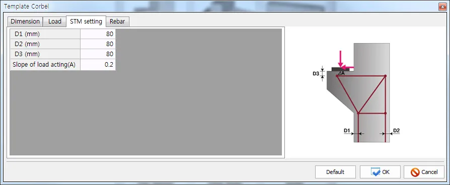
STM setting
Three reference distances D1, D2, and D3 are assigned for the automatic construction of a strut-tie model for bracket.
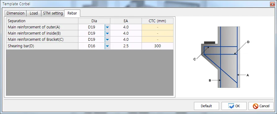
Rebar
The areas of the reinforcing bars assigned to the bracket below are recognized as the steel tie areas of the strut-tie model for a bracket. The information on the reinforcing bars can be altered, added, or deleted in the DEFINE-Tie Types-Reinforcement Ties. The information can be assigned to the elements of the strut-tie model in the ASSIGN-Tie Types.
Abutment Footing
#Dimension
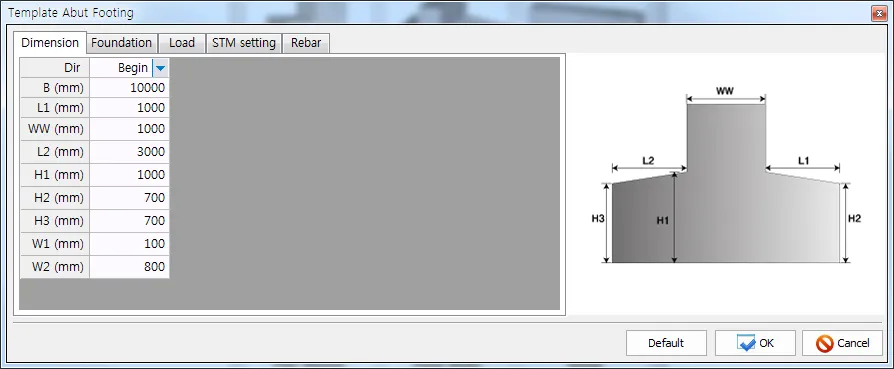
Dimension
The dimensions of an abutment footing are assigned. The boundary lines of the abutment footing are drawn according to the assigned dimensions. The loads and the area of reinforcing bars must be converted to those of the footing with 1 meter thickness since the thickness of the footing is assumed to be 1 meter. The Right in the Dir indicates that the right side of the footing is the front. On the contrary, the Left in the Dir indicates that the left side of the footing is the front. The symbol T used for calculating the soil (or pile) reaction coefficient is the thickness of the footing.
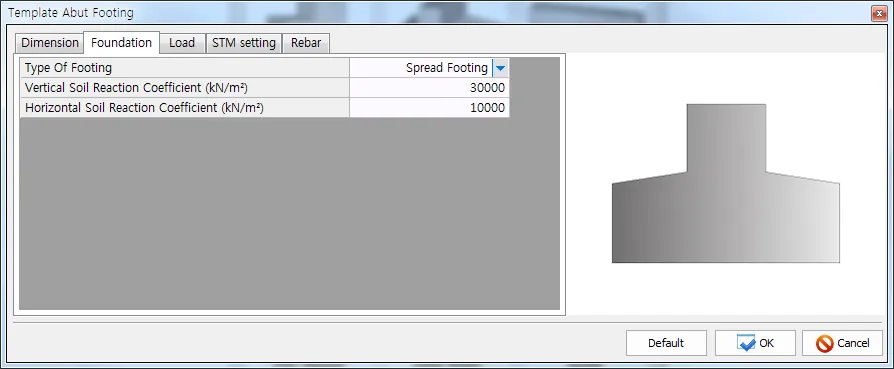
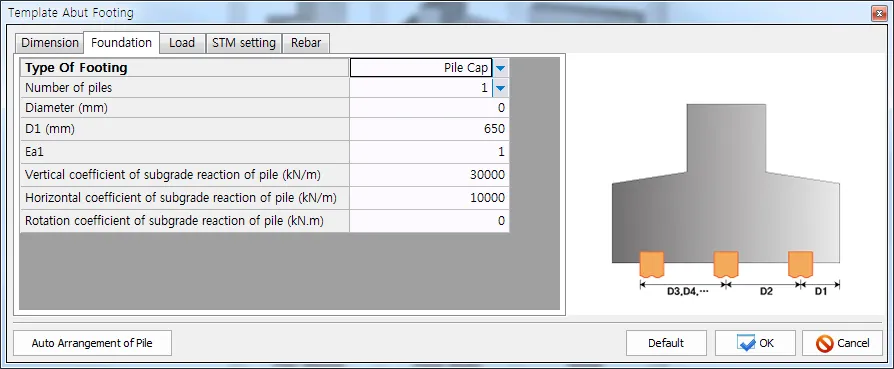
Foundation
The type of abutment footing, coefficients of soil or pile reaction per unit area, and number of piles in two horizontal directions are assigned. Two foundation types (Spread Footing, Pile Footing) are provided.
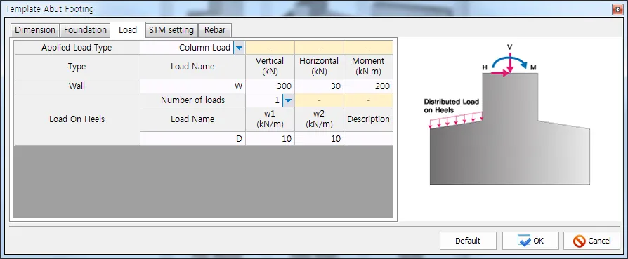
Load
The dead and live loads are assigned. After assigning the load names and description, they can be altered, added, or deleted in the DEFINE-Static Load. The positive values for vertical load, horizontal load, and moment must be assigned.
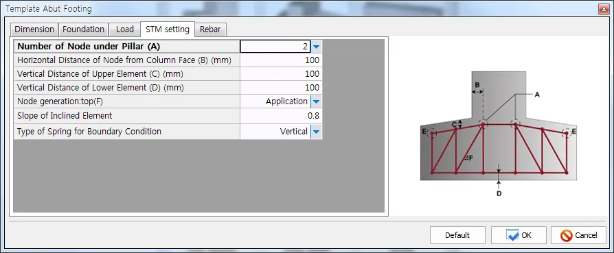
STM setting
The number of nodes below column, three reference distances B, C, and D, and the slope of inclined element are assigned for the automatic construction of a strut-tie model for abutment footing.
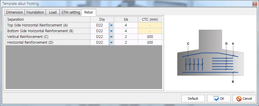
Rebar
The areas of reinforcing bars assigned to the abutment footing below are recognized as the steel tie areas of the strut-tie model for a footing. The information on the reinforcing bars can be altered, added, or deleted in the DEFINE-Tie Types-Reinforcement Ties. The information can be assigned to the elements of the strut-tie model in the ASSIGN-Tie Types.
.
Pier Coping
#Dimension
Dimension
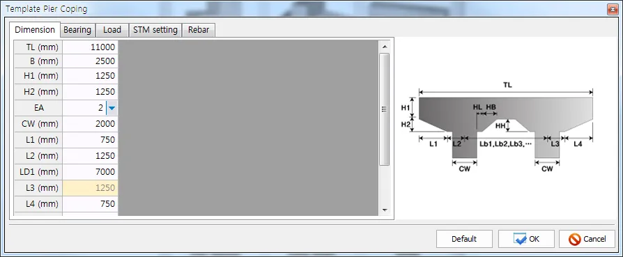
The dimensions of a pier coping are assigned. The boundary lines of the pier coping are drawn according to the assigned dimensions. The symbols T and EA are the thickness of the pier coping and the number of columns. The symbols LD1, LD2, and LD3 are the center-to-center distances of two columns in the pier coping supported by two, three, and four columns, respectively.
Bearing
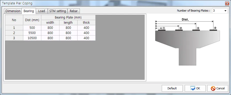
The positions and dimensions of bearing plates are assigned. The notation Dist is the distance between a load point and left edge of the pier coping.
Load
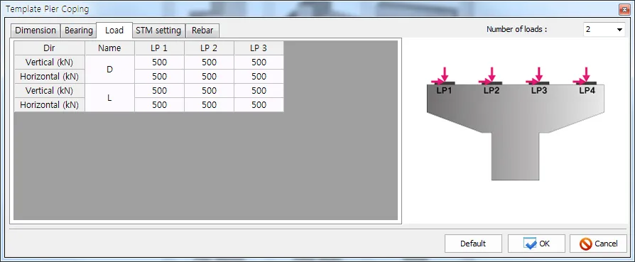
The dead and live loads are assigned. After assigning the load names, they can be altered, added, or deleted in the DEFINE-Static Load. The positive values for vertical loads must be assigned. The positive horizontal loads are set as the forces acting from left to right. The negative horizontal loads are set as the forces acting from right to left.
STM setting
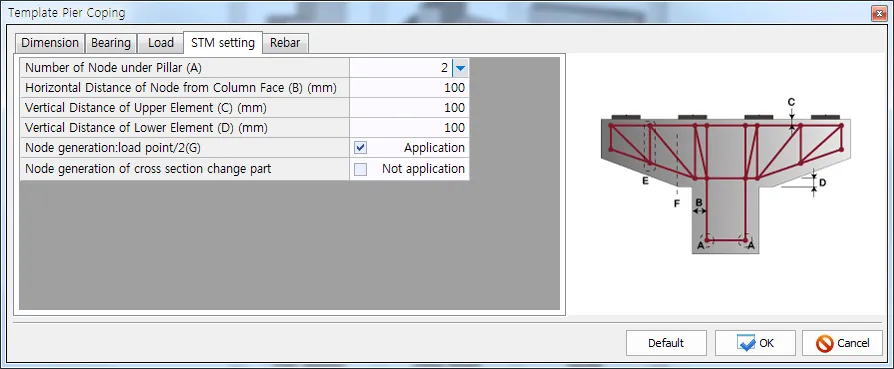
The number of nodes at column, three reference distances B, C, and D are assigned for the automatic construction of a strut-tie model for pier coping. Two nodes between two outside load points at the top and bottom of the coping can be generated.
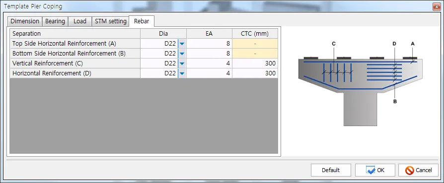
Rebar
The areas of reinforcing bars assigned to the pier coping below are recognized as the areas of steel ties of the strut-tie model for pier coping. The information on the reinforcing bars can be altered, added, or deleted in the DEFINE-Tie Types-Reinforcement Ties. The information can be assigned to the elements of the strut-tie model in the ASSIGN-Tie Types.
Pier Footing
#Dimension
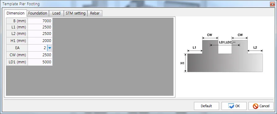
Dimension
The dimensions of a pier footing are assigned. The boundary lines of the pier footing are drawn according to the assigned dimensions. The symbols T and EA are the thickness of the pier footing and the number of columns. The symbols LD1, LD2, and LD3 are the center-to-center distances of two columns in the pier coping supported by two, three, and four columns, respectively.
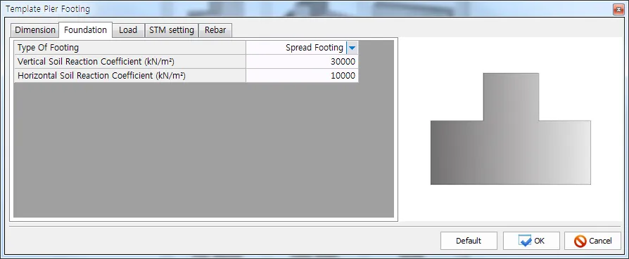
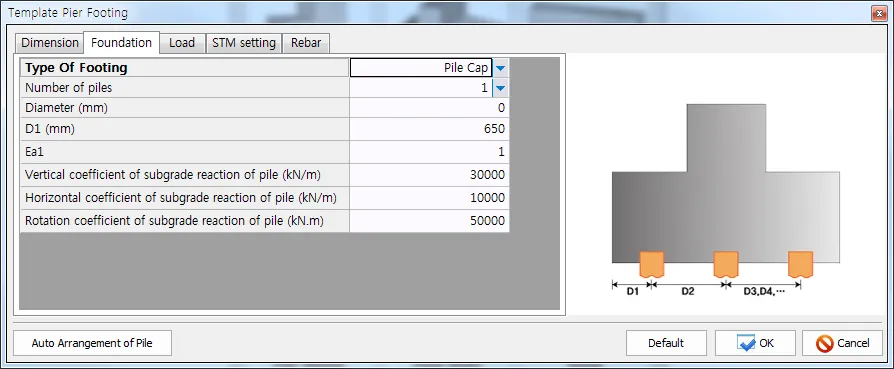
Foundation
The type of pier footing, coefficients of soil or pile reaction per unit area, and number of piles in two horizontal directions are assigned. Two foundation types (Spread Footing, Pile Footing) are provided.
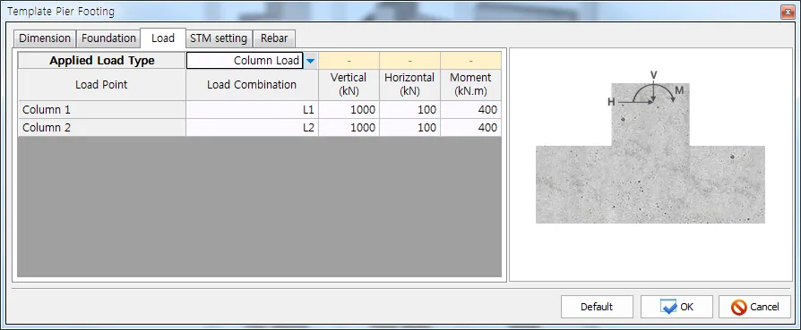
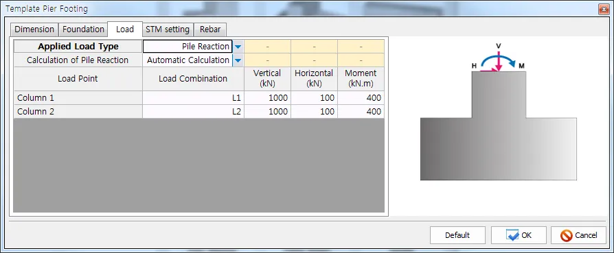
Load
The loads from column(s) are assigned. After assigning the load names, they can be altered, added, or deleted in the DEFINE-Static Load. The positive values for vertical loads must be assigned. The positive horizontal loads are set as the forces acting from left to right. The negative horizontal loads are set as the forces acting from right to left. The positive and negative moments are set as the clockwise and counterclockwise moments, respectively.
STM setting
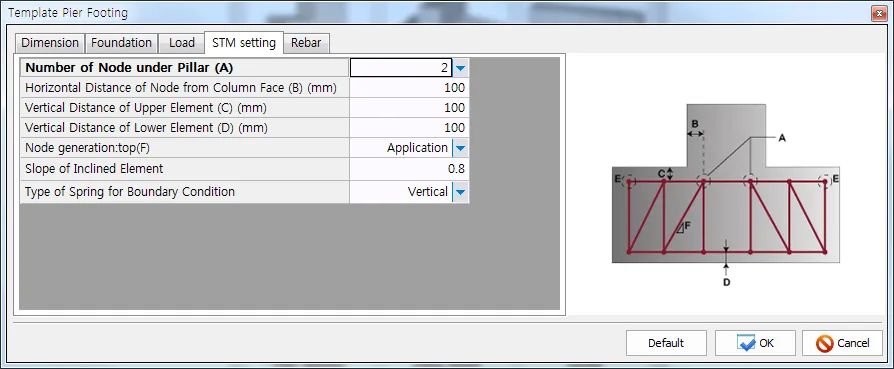
The number of nodes under column, three reference distances B, C, and D, and the slope of inclined element are assigned for the automatic construction of the strut-tie model for pier footing.
Rebar
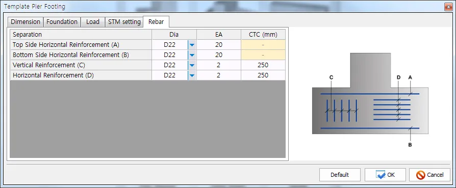
The areas of reinforcing bars assigned to the pier footing below are recognized as the areas of the steel ties of the strut-tie model for pier footing. The information on the reinforcing bars can be altered, added, or deleted in the DEFINE-Tie Types-Reinforcement Ties. The information can be assigned to the elements of the strut-tie model in the ASSIGN-Tie Types.
Frame Corner
#Dimension
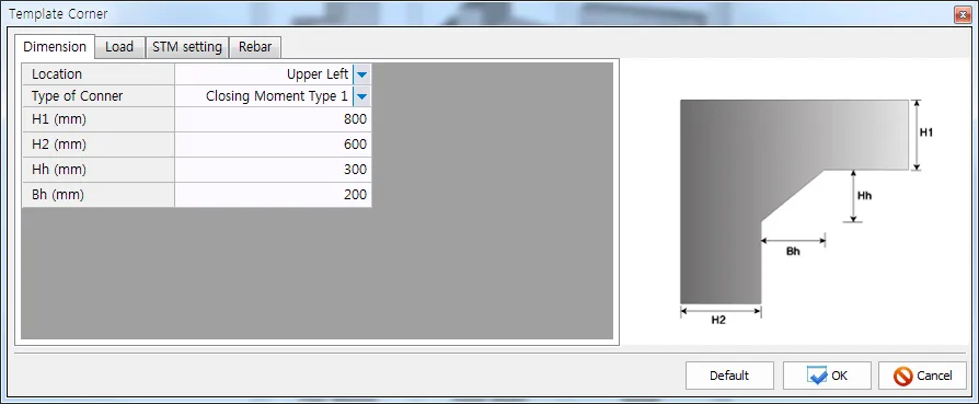
Dimension
The dimensions of four types of frame corners (Upper Left, Upper Right, Lower Left, Lower Right) subjected to opening or closing moments are assigned. The boundary lines of a frame corner are drawn according to the assigned dimensions. The loads and the areas of reinforcing bars must be converted to those of the frame corner with 1 meter thickness since the thickness of the frame corner is assumed to be 1 meter.
Load
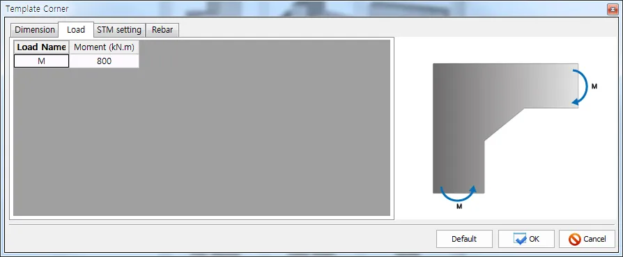
The opening moments or closing moments are assigned. After assigning the load name, it can be altered, added, or deleted in the DEFINE-Static Load. The positive moment that acts to the directions shown in the figure must be assigned.
STM setting
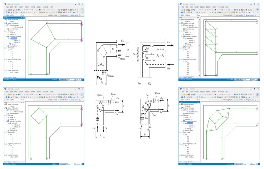
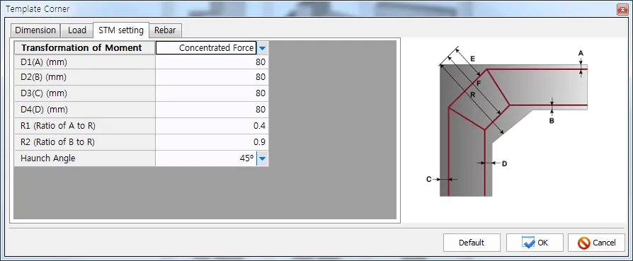
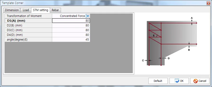
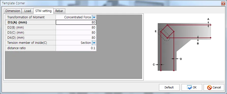
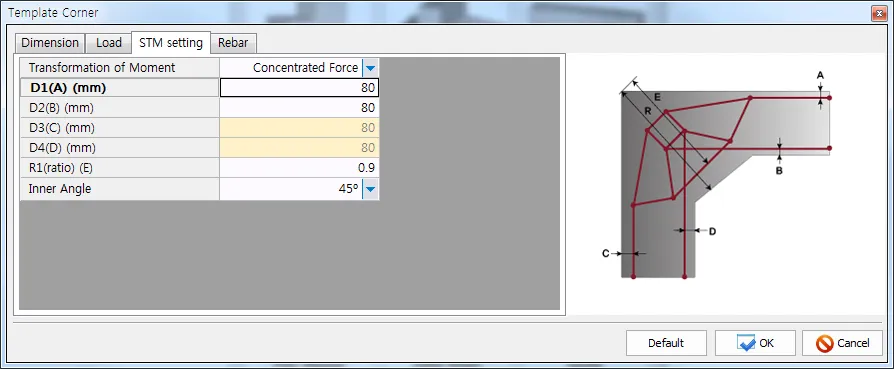
Different information according to the types of frame corners and moments is assigned for the automatic construction of the strut-tie model for frame corner. The assigned moments are converted to the distributed or concentrated forces at their corresponding sections for plane solid analysis. In the strut-tie model analysis, the moments are converted to the concentrated forces. Four types of strut-tie models under closing and opening moments on two upper left frame corners are shown below
Closing Moment Type 1
Closing Moment Type 2
Four reference distances and a truss angle are assigned for the automatic construction of the strut-tie model for the frame corner subjected to two closing moments.
Opening Moment Type1
Four reference distances are assigned for the automatic construction of the strut-tie model for the frame corner subjected to two opening moments.
Opening Moment Type 2
Four reference distances and one distance ratio are assigned for the automatic construction of the strut-tie model for the frame corner subjected to two opening moments.
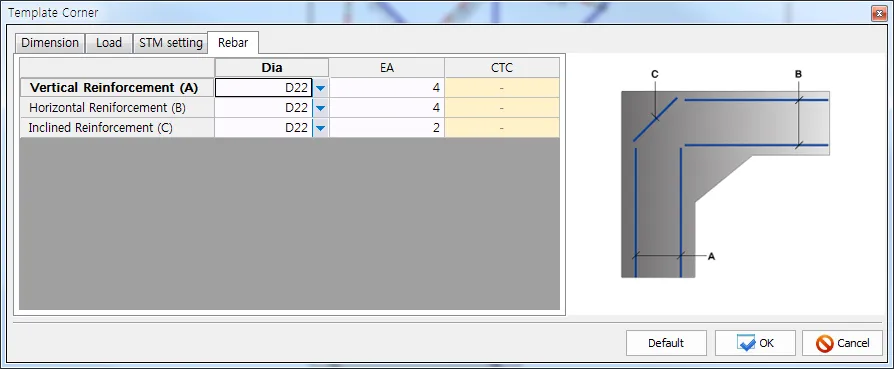
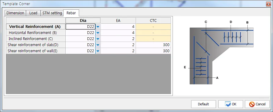
Rebar
The areas of reinforcing bars assigned to the frame corners are recognized as the steel tie areas of the strut-tie models for the frame corners. The information on the reinforcing bars can be altered, added, or deleted in the DEFINE-Tie Types-Reinforcement Ties. The information can be assigned to the elements of the strut-tie model in the ASSIGN-Tie Types.
Closing Moment Type 1
Closing Moment Type 2
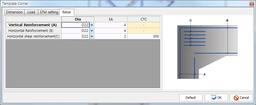
Opening Moment Type 1
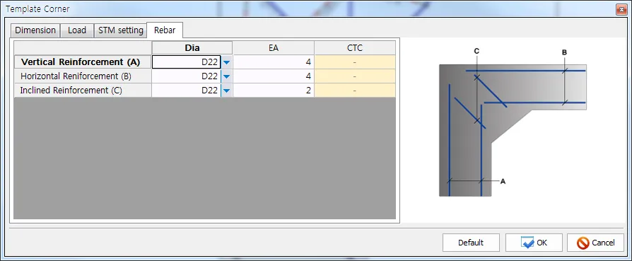
Opening Moment Type 2
Anchorage Zone with Inclined Tendons
#Dimension
Dimension
The dimensions of a PSC beam anchorage zone with inclined tendons, number of strands, and strand locations are assigned. The boundary lines and tendon layouts are drawn according to the assigned dimensions. The direction Right indicates that the compressive forces of prestressing tendons act from left to right. Two types of strut-tie models are generated: a model constructed by considering the slope of tendons and a model constructed by considering the compressive stress flows. The number of strands is limited to 20. The symbol T is the thickness of the zone.
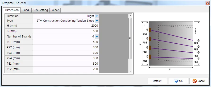
Load
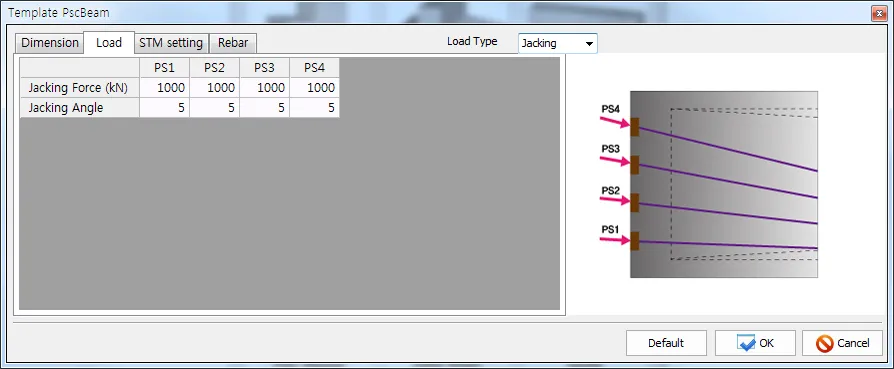
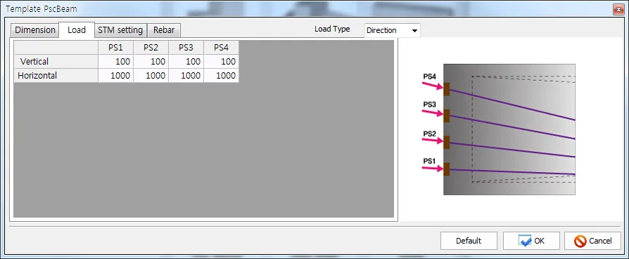
The jacking angle and forces are assigned. The positive values for the jacking forces must be assigned.
STM setting
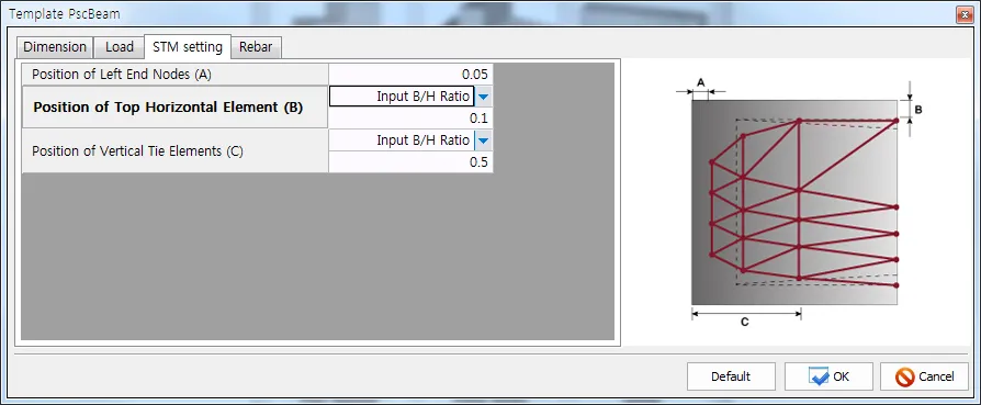
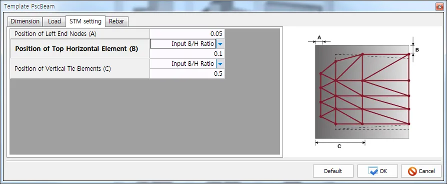
Three reference distances A, B, and C are assigned for the automatic construction of the strut-tie model for the anchorage zone with inclined tendons.
STM Construction by Considering Tendon Slope
STM Construction by Considering Stress Flows
Rebar
The areas of reinforcing bars assigned to the anchorage zone are recognized as the steel tie areas of the strut-tie model for the anchorage zone. The information on the reinforcing bars can be altered, added, or deleted in the DEFINE-Tie Types-Reinforcement Ties. The information can be assigned to the elements of the strut-tie model in the ASSIGN-Tie Types.
Anchorage Zone with Straight Tendons
#Dimension
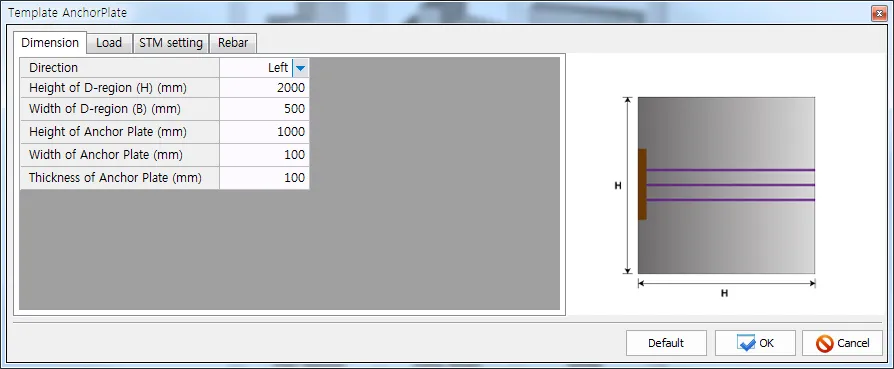
Dimension
The dimensions of an anchorage zone with straight tendon(s) and the information on a bearing plate are assigned. The boundary lines of the anchorage zone are drawn according to the assigned dimensions. The direction Left indicates that the forces by prestressing tendons act from left to right. The symbol T is the thickness of the zone.
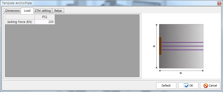
Load
The jacking force is assigned. The jacking force must be positive value.
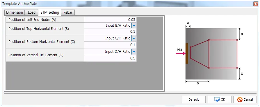
STM setting
Four reference distances A, B, C, and D are assigned for the automatic construction of the strut-tie model for the anchorage zone.
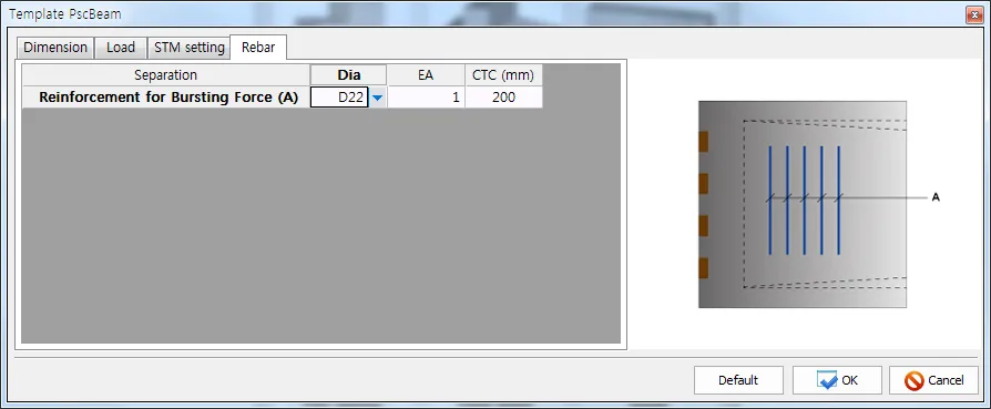
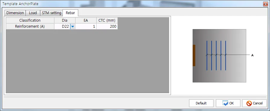
Rebar
The areas of reinforcing bars assigned to the anchorage zone with straight tendons are recognized as the steel tie areas of the strut-tie model for the anchorage zone. The information on the reinforcing bars can be altered, added, or deleted in the DEFINE-Tie Types-Reinforcement Ties. The information can be assigned to the elements of the strut-tie model in the ASSIGN-Tie Types.
Deep Beam with Concentrated Loads
#Dimension
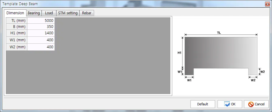
Dimension
The dimensions of a deep beam are assigned. The boundary lines of the deep beam are drawn according to the assigned dimensions. The symbol T is the thickness of the beam.
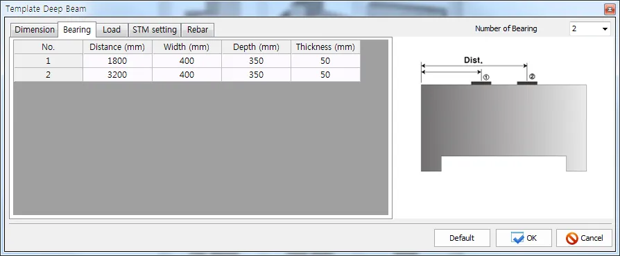
Bearing
The information on the bearing plates are assigned here. The information can be altered in the ASSIGN-Bearing Plates after clicking the strut-tie model node framed by the bearing plate.
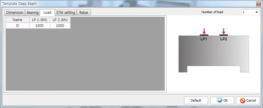
Load
The vertical loads acting on bearing plates are assigned. After assigning the load name, it can be altered, added, or deleted in the DEFINE-Static Load. The positive loads that act to the directions shown in the figure must be assigned.
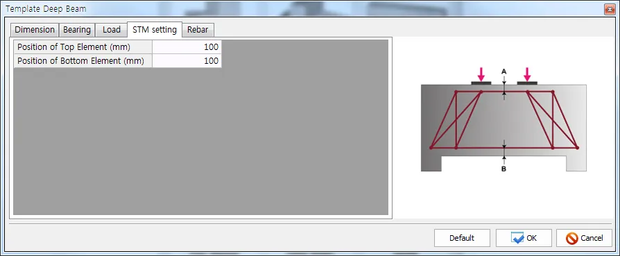
STM setting
Two reference distances are assigned for the automatic construction of the strut-tie model for the deep beam.
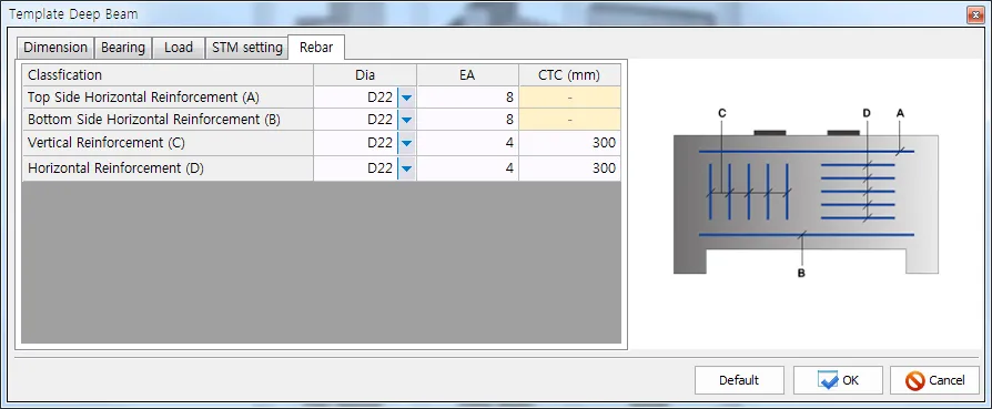
Rebar
The areas of reinforcing bars assigned to the deep beam are recognized as the steel tie areas of the strut-tie model for deep beam. The information on the reinforcing bars can be altered, added, or deleted in the DEFINE-Tie Types-Reinforcement Ties. The information can be assigned to the elements of the strut-tie model in the ASSIGN-Tie Types.
Girder
#Dimension
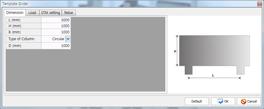
Dimension
The dimensions of a girder and information on the supporting columns (circular, square, rectangle) are assigned. The boundary lines of the girder zone are drawn according to the assigned dimensions. The symbol T is the thickness of the beam.
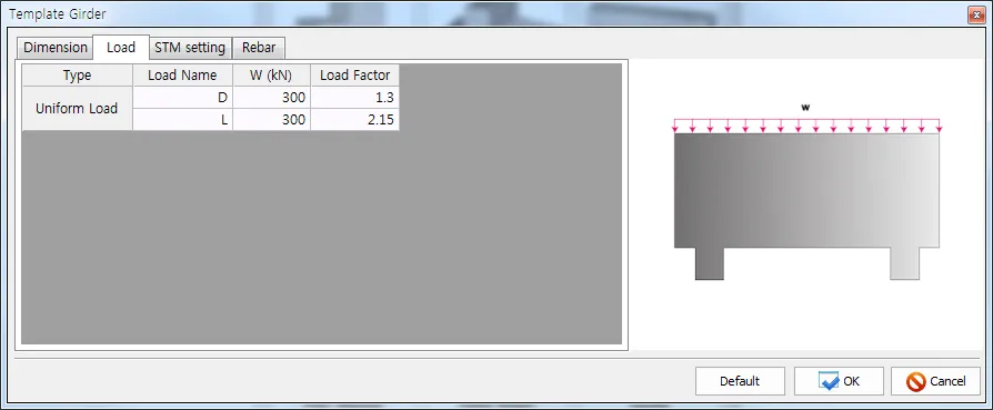
Load
The information on the distributed load is assigned. The load name and load combination can be altered, added, or deleted in the DEFINE-Static Load and DEFINE-Load Combinations, respectively. Presently, the program allows only two load types and one load combination.
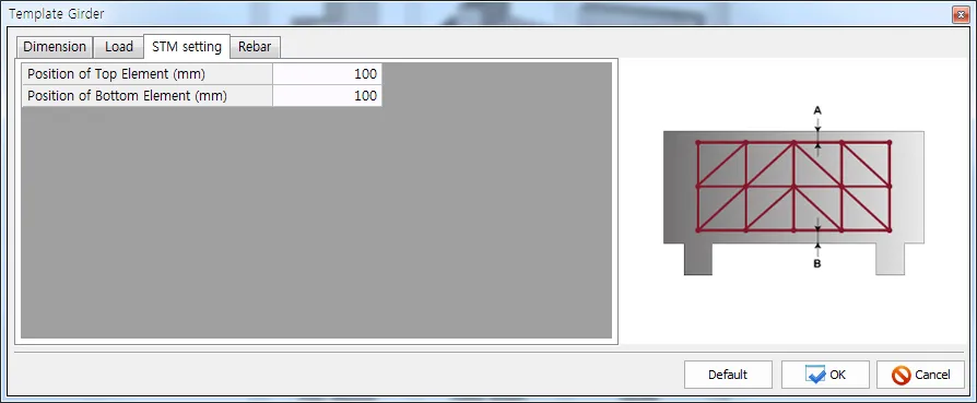
STM setting
Two reference distances are assigned for the automatic construction of the strut-tie model for the girder.
Rebar
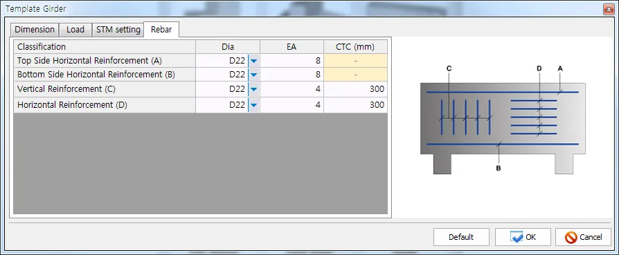
The areas of reinforcing bars assigned to the girder are recognized as the steel tie areas of the strut-tie model for girder. The information on the reinforcing bars can be altered, added, or deleted in the DEFINE-Tie Types-Reinforcement Ties. The information can be assigned to the elements of the strut-tie model in the ASSIGN-Tie Types.
STM information

What is STM?
https://www.astruttie.com/ko/learn
STM design process
https://www.astruttie.com/ko/learn
Evolutionary Structural Optimization(E.S.O) Method
https://www.astruttie.com/ko/learn
Design Example

Design of deep beams subjected to concentrated load (1)
https://www.astruttie.com/ko/learn
Design of deep beams subjected to concentrated load (1)
https://www.astruttie.com/ko/learn
Design of deep beams subjected to concentrated load (1)
https://www.astruttie.com/ko/learn
Design of deep beams subjected to concentrated load (1)
https://www.astruttie.com/ko/learn
Bridge Pier, Hammerhead Bent Cap, ACI SP273-1
https://www.astruttie.com/ko/learn
Output Report

Design Report (ACI 318-14) – Deepbeam
https://www.astruttie.com/ko/learn
Design Report (AASHTO LRFD) – Deepbeam
https://www.astruttie.com/ko/learn
Design Report (Eurocode 2) – Deepbeam
https://www.astruttie.com/ko/learn