.bri
Steel composite bridge design
Steel composite bridges for road and rail in one flow — from alignment input to drawings and quantities.
Steel Box-Girder Bridge Design Software for the Latest Design Codes
Key features
- Steel box and plate-girder bridges
- Alignment- and cross-section-based modeling
- Calculation reports with steel, weld, and paint schedules
- General and detail drawings to DXF
Product introduction
Introduction
Overview
First released in 1998, ARoad is design-automation software dedicated to steel box-girder bridges in Korea.
On the road-bridge base it added, as modules, ARail for railway bridges (December 2004), ARoadDeck for deck reinforcement drawings and general quantities (August 2005), OpenBox for open-top sections (July 2013) and LSD for the Korean Highway Bridge Design Code 2015 (Limit State Design, April 2015).
The LSD module supporting the 2015 commentary is available from ARoad 2015. Curved bridges are checked to the Steel Structure Design Code 2014.
Steel composite bridges to the limit state method are designed and checked quickly.
Present Status
Some 200 firms in Korea use about 300 licenses. Its deliverables have been proven on many projects over the years, and continuous upgrades have raised its quality.
ARoad is widely used for steel box-girder bridge design in Korea.
Features
Special Features
Since 1998 ARoad has kept pace with the design codes and added functions: the Korean Highway Bridge Design Code 2010 and 2015 (Limit State Design), and the Railway Bridge Design Codes 2011 and 2013.
Detailed design by span, girder and support. Options, defaults and automation buttons make the many inputs easier.
Design review through the calculation report, summary drawings and user design checks.
▶ Alignments
Most horizontal alignments used on roads, railways, subways and light rail: clothoid, egg, double-egg, S-curve and transition curves.
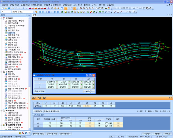
▶ Sections
Standard, trapezoidal, one-sided trapezoidal and road-crossfall sections. Closed, open and mixed top plates (OpenBox module).
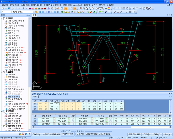
▶ Top-plate bracing
Lateral bracing to connect the separated top plates of open sections (OpenBox module). SD- and X-type bracing with various rolled sections. Connection directly to the top plate, through gusset plates on the top plate, or through gusset plates on the web.
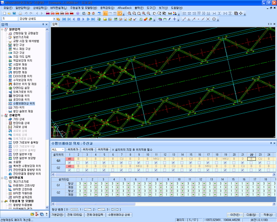
▶ Open zones
Open zones and top-plate width changes. Width changes inside the webs or on both sides. Closed and open zones set freely through width input.
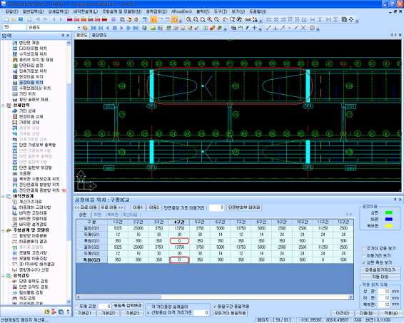
▶ Top-plate width change
Inside and both-side width changes on open-top bridges.
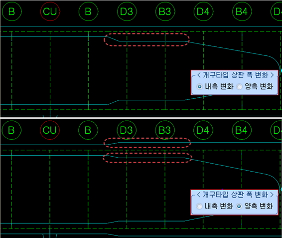
▶ Cross-section layout
Footways, barriers, noise barriers, medians and carriageways for road bridges; ballast, curbs and cable troughs for railway bridges (Rail module) — close to the real layout.
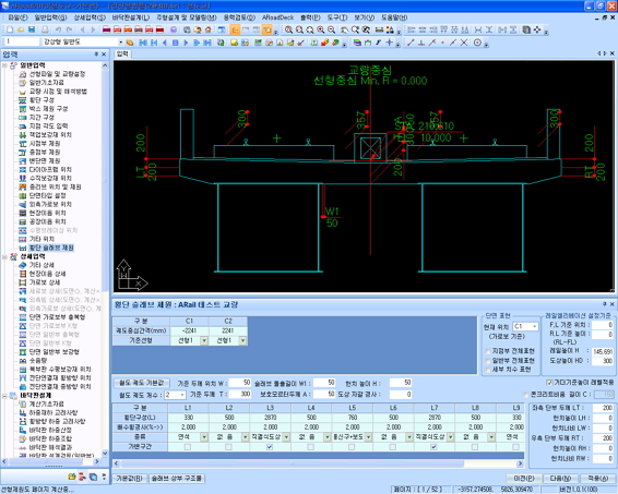
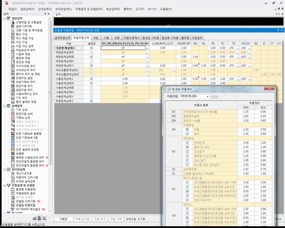
▶ Loads
Switch each load type on or off. Choose distributed or concentrated loads in the editor. Set whether and in what proportion each load enters a combination.
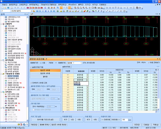
▶ Load combinations
Combinations and factor adjustment per limit state (Limit State module).
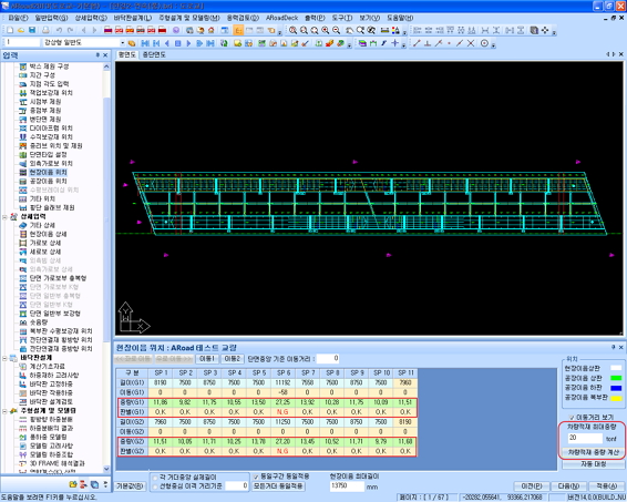
▶ Transport weight
A “vehicle load weight” check button in the general input shows the transport weight by position.
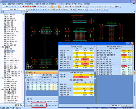
▶ Design check
User design checks for closed and open field splices for quick review.
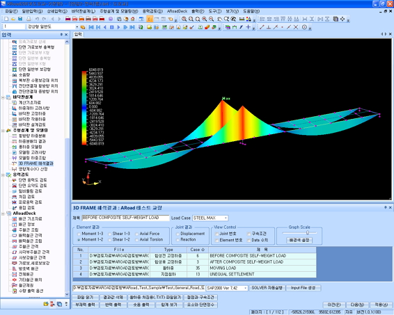
▶ Grillage analysis
View 3D frame analysis results from SAP2000.
▶ Design check
Design review of sections, stiffeners and field splices (Limit State module).
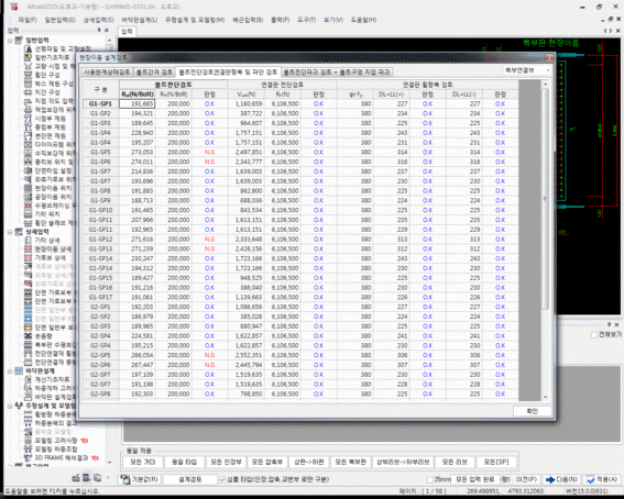
▶ Section check
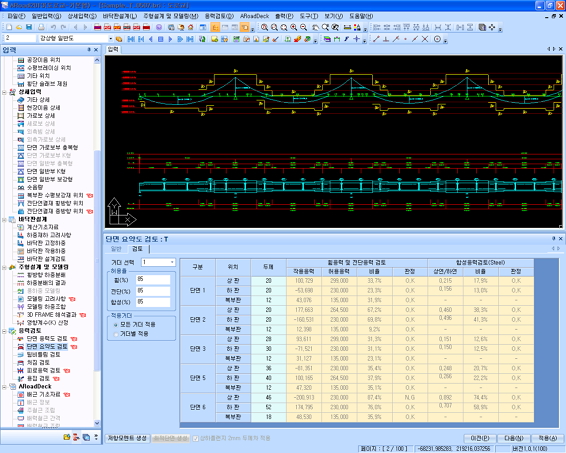
Section properties, applied stresses and resistances in one dialog. Results by position in the section-check table.
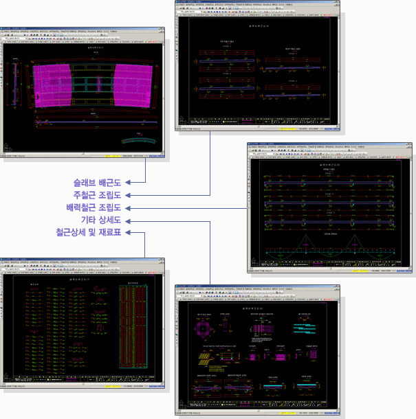
Deck module
Fast, simple input
-ARoad data used directly for slab design, with no conversion to BRX or other files.-Earlier deck design results applied automatically to the slab drawings.-Steel dead-load results make it easy to position distribution bars at intermediate supports.-Reinforcement drawings matched to the deck type (road, railway).
More convenience
-Overall quantity summary across several bridges (planned).-Click to add cross-beam and stringer reinforcement details anywhere.-Bar trim zones and user-defined zones.-Lap lengths shown automatically on the main-bar assembly drawing from stock bar length.-Distribution-bar assembly drawings generated from the distribution and main-bar spacing.
Your own style
-Main-bar spacing edited and adjusted in detail by the user.-Strength design and the empirical method, with a wide range of main and distribution bar inputs.
Drawing deliverables
Quantity deliverables
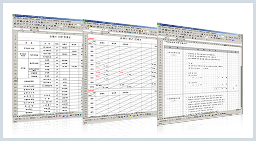
-NDT summary and NDT calculation basis from the welding quantities.
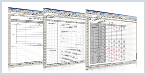
-General quantity summary, reinforcement quantity summary, general quantity calculation basis.